An Interesting Attempt to Extract the Utmost Possible Heat From the Steam

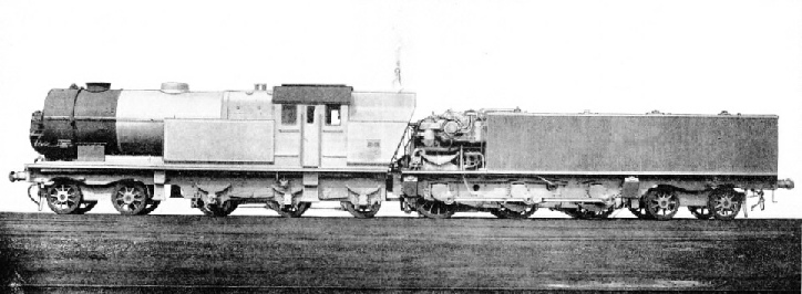
The British “Ljungstrom” Locomotive, showing its massive proportion and its many interesting external features.
CONSIDERABLE interest has been aroused by tests made between Derby and Manchester by the LMS Railway of a “Ljungstrom” turbo-condensing locomotive lent to them by the makers, Beyer, Peacock & Co. Ltd, Manchester. Although built to the general requirements of the inventors and manufacturers of the original “Ljungstrom” turbine-driven locomotive, built in Sweden some years ago, substantial modifications in design have been made by the British firm in order that this new example of the type should conform to the standard conditions of service obtaining on British railways.
The new locomotive is 74 ft in length over buffers, and in working order weighs 143 tons 14 cwt. It consists of two vehicles, the first carrying the boiler and the second the turbine and condenser. The former is carried on three fixed axles and a leading sliding-type four-wheeled bogie, and the ten wheels are each 3 ft 3-in in diameter.
The boiler is of the ordinary locomotive type, having a Belpaire firebox and steel inner firebox with steel stays. It has an outside diameter of 6 ft and contains 238 2½-in diameter steel tubes, while the superheater is a M.L.S. small tube type. The boiler is built for a working pressure of 300 lb per sq in. Details of the heating surface are:-
Tubes: 1,480 sq ft.
Firebox: 140 sq ft.
Superheater: 640 sq ft.
Total: 2,260 sq ft.
The grate area is 30 sq ft.
Access to the boiler tubes is facilitated by the front portion of the smoke box, wherein is the preheater, being set up on hinges.
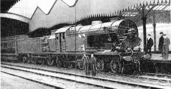
The air-preheater is of the “Ljungstrom” patent type and has a heating surface of roughly 13,500 sq ft. The nickel blades of the turbine rotor it contains are alternately heated and cooled by hot gases and incoming air respectively, the latter being induced by a turbine-driven draught (an attached to the front of the smokebox, as shown in our illustration. This fan can be controlled from the footplate by the fireman.
The boiler and turbine are connected by ordinary piping, a ball-and-socket joint allowing for movement between the two vehicles. Two regulators are fitted; one that remains full open when the engine is in service is in the dome, and the other, for regulating the admission of steam to the turbine blades, is adjacent to the main turbine.
At the rear of the boiler-carrying vehicle is a coal bunker to accommodate six tons of fuel, while side tanks to hold 600 gallons of water are fitted at the sides of the boiler. Between the boiler and the coal bunker is the engine cab or footplate, the size of which is in keeping with the generous lines of the whole locomotive.
The second vehicle takes the place of the tender to the usual locomotive and has three pairs of coupled driving wheels, 5 ft 3-in in diameter, followed by a four-wheeled bogie to facilitate the rounding of curves. In the fore part of the vehicle and coming immediately behind the coal bunker is the main turbine. This drives the front pair of coupled wheels through direct double helical three-reduction gearing having a ratio of 1 to 25.22, the final drive to the driving axle from the last gear shaft being effected by a quill-type axle. The turbine runs in one direction only and reversal is carried out from the cab by hand gearing operating an idle shaft and gears. Motion is imparted to the intermediate and trailing coupled wheels by means of side coupling rods having outside cranks.
Dust-proof casing encloses the main gearing and is largely responsible for filling the space between the driving wheels. As a result the main frames, with external axle boxes and crank arms, are placed outside the wheels. The gear casing is attached to the main frames so as not to impede any movement of the latter.
The main turbine is of the axial flow type and capable of developing 2,000 hp at 10,000 revs per minute, the equivalent engine speed being 70 miles per hour. Flexible couplings link the turbine with the main gearing.
The condenser immediately behind the turbine is of the “Ljungstrom” patent air-cooled type ,with auxiliary surface condenser, and includes some 2,500 flattened and ribbed copper tubes ranged vertically in groups on both sides. Steam is led from the turbine exhaust to top-collectors of the condensers and condensation is effected by drawing air between the tubes at a prescribed velocity, four 6 ft 9-in diameter turbine-driven draught fans operating from a separate turbine being used to achieve this. The condensate is received by bottom-collectors and passed to a sump, from which a diffuser returns it to the condenser body.
The capacity of the main condenser body is roughly 1,350 gallons of water, and the boiler is fed from this by two turbine-driven centrifugal pumps. Water is drawn from the side tanks on the front vehicle to compensate for the minor losses resulting from whistles, etc, and its admission to the condenser is regulated by a valve placed on the footplates.
In conclusion, braking is effected on the locomotive by a steam and hand-brake on the boiler-carrying portion and by a vacuum brake on the condenser vehicle. This latter type of brake can also be used for the train.
It is interesting to note that this locomotive is at present engaged in passenger service between Derby and Birmingham, and will shortly be running express trains between Manchester, Derby and London.
The thermal efficiency of the steam locomotive is low on account of the large amount of heat that goes to waste by way of the chimney. The great possibilities of the turbo-condensing locomotive in producing a higher thermal efficiency, by extracting the utmost possible heat from the steam, have been realised for many years and various engines of this type have been designed and constructed.
Among these engines may be mentioned the “Reid-MacLeod” geared turbine condensing locomotive, built by the North British Locomotive Co. Ltd, of Glasgow, in 1924. This engine differs from the “Ljungstrom” turbo-condensing locomotive in many respects, notably in that its turbines are placed longitudinally. The driving wheels are actuated directly from the turbines and there is a complete absence of reciprocative motion.
In Germany also a good deal of experimental work has been carried out in regard to this type of engine. In 1924 Messrs. Krupp constructed at their Essen Works a turbine locomotive embodying many interesting features, and for this engine a reduction of 20 per cent, in fuel consumption was claimed. More recently, Messrs. J. A. Maffei of Munich constructed a turbine engine on somewhat similar lines to the Krupp locomotive. This engine, which was designed to develop 2,500 hp and to have a maximum speed of approximately 75 miles per hour, underwent extensive trials last year on the Bavarian section of the German State Railways.

View showing the front of the locomotive.
You can read more on “Experimental Locomotives”, “Giant American Locomotives” and “The Poultney Locomotive” on this website.
You can read more on “Turbine Driven Locomotive” and “The Turbine Locomotive” in Wonders of World Engineering


