© Railway Wonders of the World 2012-


Part 29


Part 29 of Railway Wonders of the World was published on Friday 16th August 1935.
This issue contained a photogravure supplement on Clearing the Line. This formed an article in its own right, and appeared on pages 915-18.
The Cover
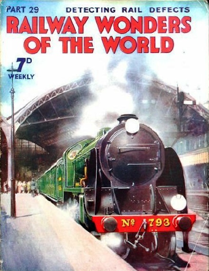
Our cover this week shows a Southern Railway express hauled by a “King Arthur” class engine leaving Victoria Station, London. This class of locomotive has two cylinders measuring 20½ in by 28 in, 6 ft 7 in driving wheels, and a working steam pressure of 200 lb per square inch. The engine and tender in working order weigh 138½ tons, and the total heating surface is 2,215 sq ft.
Time Tables (Part 2)
Early and modern guides to railway services. Concluded from part 28.
(Pages 901-905 )
Clearing the Line - 2
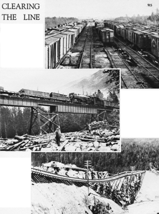
AFTER A WASH-OUT. A wash-out is caused by heavy falls of rain, snow, or rock damming the natural outlet of streams, which then race down in a torrent. The top picture shows a railway yard at Coquitlam after a torrent has swept through it, twisting the track and damaging the goods vans standing in the yard.
A TRAIL OF DESTRUCTION left behind after a mighty torrent has swept on its savage journey, is shown in the middle photograph. But the trains must run. The engineers must work day and night to clear the road. The illustration below shows part of a mountain-division track after a wash-out. No time was lost in erecting the temporary track that ca be seen above the wrecked line.
(Page 915)
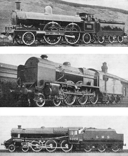
FOR MIXED TRAFFIC. A 4-6-0 locomotive designed by Mr W. A. Stanier for general utility on the LMS in 1934. The two cylinders are 18½ in by 28 in, and the coupled wheels are 6 ft in diameter. The total heating surface is 1843.5 sq ft, the grate area 27.8 sq ft, the boiler pressure 225 lb per sq in, and the weight of engine and tender in working order 126 tons 2 cwt. Seventy of these efficient locomotives were built in 1934, and they now work all over the LMS system. Despite their small driving wheels, they are capable of speeds in excess of eighty miles an hour.
(Page 928)
Locomotives of the LMS - 1
GREATER BRITAIN”, a Webb three-cylinder compound, built in 1891. The two pairs of uncoupled driving wheels were
7 ft 1 in diameter. Two high-pressure cylinders, each 15 by 24 in drove the rear pair of driving wheels, and one low pressure cylinder, 30 by 24 in, drove the front pair of driving wheels. The boiler had a heating surface of 1,505 sq ft. The weight of the engine and tender, in working order, was 79 tons
7 cwt.
ONE OF THE “BABY SCOTS”. These 4-6-0 locomotives, among the most successful passenger engines ever produced by the LMS or its constituent companies, are officially rebuilt “Claughtons”; but the rebuilding has been so drastic that they are virtually new engines. Principal dimensions are: three cylinders 18 by 26 in, driving wheels 6 ft 9 in; heating surface 2,098 sq ft; boiler pressure 200 lb per
sq in; weight of engine and tender in working order 123 tons 8 cwt.
Contents of Part 29
Time Tables (Part 2)
New York’s Life-Line
During the Rush Hours
Clearing the Line (photogravure supplement)
Detecting Rail Defects
The Story of the LMS (Part 1)
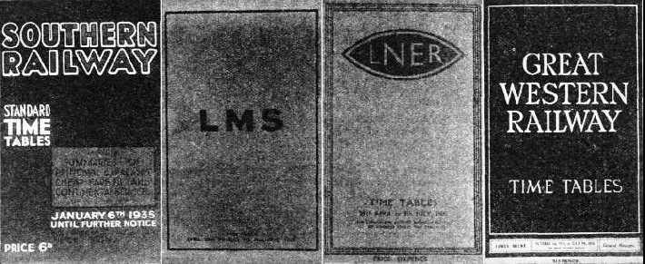
Modern Time Table Covers
SEVERE SIMPLICITY is the keynote of the modern covers illustrated here. Each of the four great British railways has chosen a colour resembling or suggesting the colour of its passenger stock. Thus, the Southern cover is mainly green, the LMS cover mainly red, and the Great Western cover "cold tea and cream." The varnished teak of the LNER carriages is suggested by the orange tint of its time-
(Page 905)
New York’s Life-Line
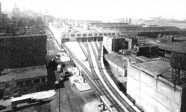
An all-freight service above city streets. The West Side Line of the New York Central Railroad Company is one of the world’s most unusual lines. It carries no passengers, but it is highly important because New York relies to a considerable extent upon this route for its food supplies. One feature of this branch of the New York central lines is that the track runs through private factories and warehouses.
(Pages 906-909 )
St John’s Park Terminal
ST. JOHN'S PARK TERMINAL, with the recently constructed viaduct and the tracks spreading out into eight lines as they enter the station. The terminal is one of the chief features of the New York Central Railroad's West Side freight line. With three stories and a basement, the building -
(Page 906)
During the Rush Hours
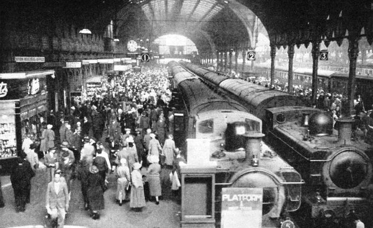
How the railways serve their regular passengers. No one likes the rush hour, but it seems always to be with us, and we are apt to think of it as a necessary evil and to forget that the railway companies throughout the world fight an unceasing battle against it. This chapter shows that enormous sums of money have been spent in recent years on laying additional running tracks, enlarging stations, and in lengthening platforms to cope with the peak traffic which occurs during four or five hours out of every twenty-four.
(Pages 910-914 )
Paddington Station During the Rush Hours
AT PADDINGTON. The London terminus of the Great Western Railway has twelve terminal platforms to deal with long-
(Page 910)
Clearing the Line
The central photogravure supplement to this part forms a tribute to the engineers of the Mountain Division of the Canadian Pacific Railway. The photographs show some of the difficulties that face the engineers of a division that has never lost a passenger’s life. This supplement complements the one which appeared in part 3 on Floods, Fire and Eathquake.
(Pages 915-918 )
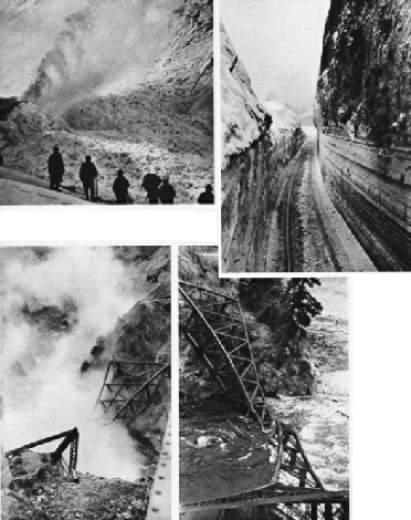
Clearing the Line - 3
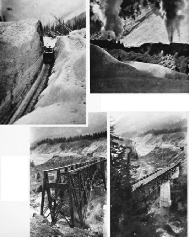
(Top) THE GREATEST MENACE against which the Canadian pacific engineers have to contend is that of snow. The centre of these three illustrations shows a rotary plough, in front of a pusher engine, working through a tremendous snowdrift. A wedge plough (left) then cleans the cut. The right-hand picture shows the track clear and ready for service.
(Bottom) A REMARKABLE ENGINEERING FEAT was carried out at Salmon River in March, 1930, without one train having been cancelled. These four illustrations show how a bridge was demolished and a new one erected in its place, and put into service on the same day. The partly demolished bridge is shown in the first of these pictures, looking from left to right. The second picture shows the new one. The third illustration is of the old structure at the moment of its demolition. Having served its time the bridge falls into the Salmon River (extreme right).
(Pages 916-917 )
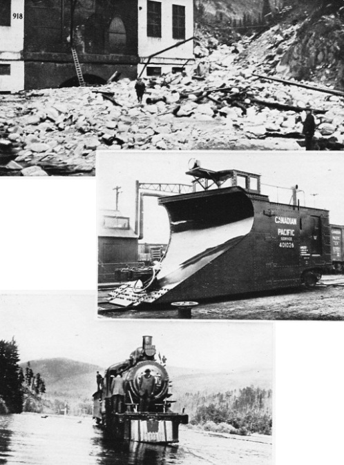
Clearing the Line - 4
A STRIKING EXAMPLE of the skill with which the Canadian Pacific Railway clears its tracks is shown in the top picture of the west portal of the Connaught Tunnel - the longest tunnel in Canada. This portal was filled to the brim, as shown, when the head waters of the Illecillewaet River broke loose and brought down with them the debris seen. The line was clear again in five days - a remarkable achievement and one of which the Canadian Pacific engineers might well be proud.
ONE OF THE WEAPONS AND ONE OF THE BATTLES. The second picture shows a ingle-track wedge snow plough used to clean the track. The third picture illustrates a locomotive negotiating a flooded track. Avalanches, floods, old bridges that have now become out of date, and a hundred other problems must be faced by the engineers of the Canadian Pacific in their ceaseless work of keeping the giant trans-continental expresses to their schedules.
The Sperry Detector Car
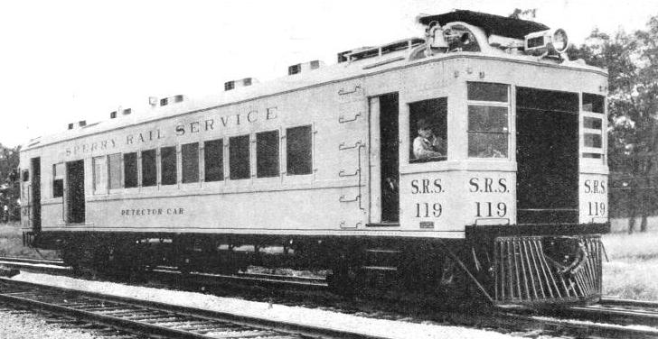
THE SPERRY DETECTOR CAR, when in service, moves over the track to be tested at a speed of five to nine miles an hour. When not engaged in detection, the car can do a speed of sixty miles an hour. The driving mechanism is a 220-
(Page 919)
The Story of the LMS (Part 1)
The nation-
concludes in part 30.
(Pages 910-
You can read more on LMS steamship services in Shipping Wonders of the World.
Detecting Rail Defects
Remarkable safety apparatus that discovers invisible flaws. This chapter explains how hidden flaws in rails are detected by electricity. The transverse fissure, which is the most dangerous type of flaw, is most prevalent in America, where considerable progress has been made in this vital mater of safeguarding the permanent way. The late Dr Elmer Sperry, a famous inventor, discovered a method of detecting internal fissure in rails. The results of Dr Sperry’s work are the main subject of this chapter, and his Sperry Rail Service Corporation. The article was written by Cecil J. Allen, and was the eleventh article in the series Design and Invention.
(Pages 919-924 )
