
© Railway Wonders of the World 2012-


Rack Rail Locomotives
Carrying Trains Over Mountainous Gradients
THERE are definite limits to the climbing powers of any conventional type of locomotive. When the gradient becomes too steep the adhesion is insufficient to move the train, and the wheels “spin” idly on the rails. Whenever possible, therefore, mountain railways are built with wide sweeping curves or spiral tunnels to gain height with the easiest gradient that circumstances permit. Often, however, the engineer has no alternative but to scale the mountain-
The most common form of mountain-
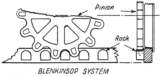
PATENTED IN 1811. A simple form of rack rail invented by John Blenkinsop was used on a colliery line so that heavier loads might be drawn. In 1829 a train of 140 tons is believed to have been drawn by a Blenkinsop locomotive up an incline of 1 in 440 at about three miles an hour. This was a considerable feat at that time.
In a report made to the directors of the Liverpool and Manchester Railway it is recorded that in March, 1829, a Blenkinsop locomotive had drawn a load of thirty-
F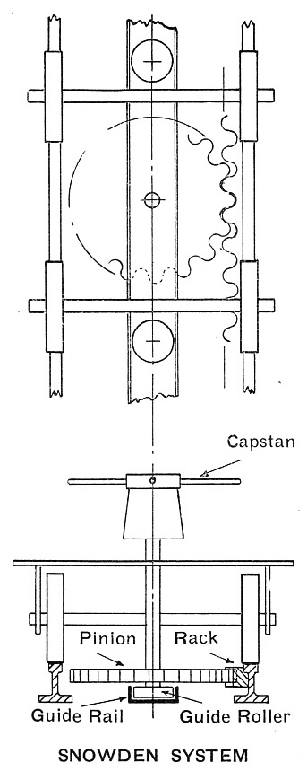 ollowing on Blenkinsop’s invention, patents were granted in 1824 to a Mr. Snowden for a rack rail that in essential principles had a counterpart in the Locker system used on the Pilatus railway over sixty years later.
Snowden’s scheme, however, was not intended as an aid to steam locomotion, but was definitely a move for its abolition and the substitution of cars propelled manually. A pamphlet published in 1834 makes interesting and somewhat amusing reading. The front cover of the booklet reads as follows:
“Manual labour superior to steam used upon railways.
“A new discovery whereby manual labour can be most advantageously substituted for steam power upon railways, as being greatly preferable, and much cheaper, thereby removing the use of horses for conveyance of goods and passengers, by which means ample employment would be supplied for all industrious labourers throughout the country; being an exposition of the merits and national importance of Mr. Snowden’s Patent improvements in Railways and Carriages and their easy adaptation for every road in the empire, on account of their simplicity, efficiency, and extraordinary cheapness. (Before you doubt -
“London. Printed by J. Tenten, 190 Drury Lane, and published by Effingham Wilson, Royal Exchange, 1834.”
A RACK-
Snowden suggested the use of a pair of flat-
The wagon was to have flangeless wheels. To keep it on the track rollers were fitted at either end, to run in the central hollow rail.
To propel the wagon a toothed wheel on the lower end of a vertical shaft engaged with the rack. To the upper end of the shaft was to be fitted a winch or capstan turned by four men.
It was proposed that this rack-
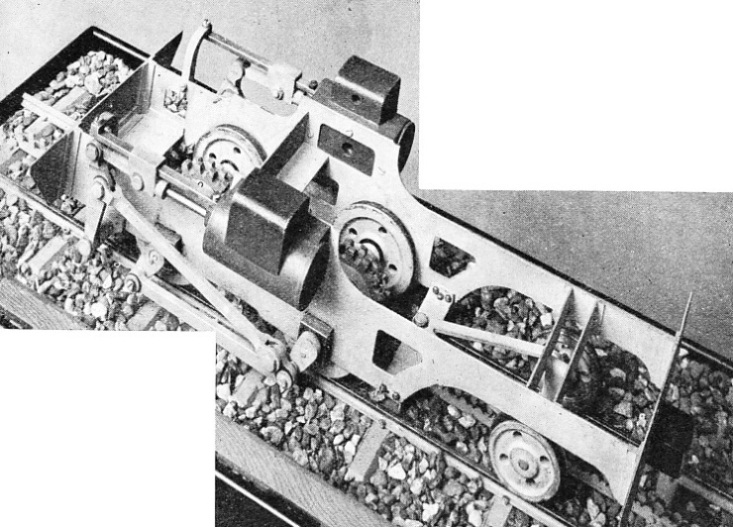
In 1836 a rack locomotive was built at the Neath Abbey works for the Dowlais Ironworks. This engine had outside cylinders driving the rear wheels together with a pinion wheel gearing with a rack laid between the rails. The pinion wheel could be lifted up on level stretches of line not provided with a rack.
Two years later the Neath Abbey works built a particularly interesting rack engine for the Rhymney Iron Company. This locomotive was probably one of the earliest articulated engines, and was carried on two four-
At Madison, USA, two Baldwin locomotives were put into service for operating a stretch of rack line in 1848. These engines had eight-
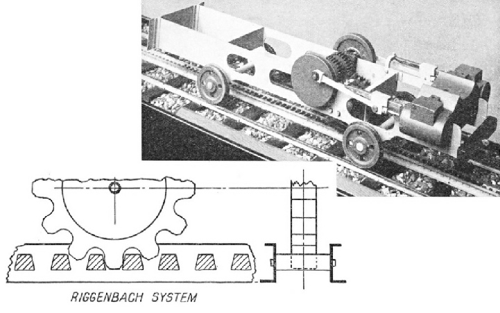
A GRADIENT OF 1 IN 10 was overcome by Riggenbach on a railway near Vienna. The rack on this line was laid between the rails and constructed in the form of a ladder with iron rungs riveted into the webs of shaped girders, placed back to back and 5-
In 1874 M. N. Riggenbach built a standard-
A model of the gearing and framework of an engine used on this line may be seen at the Science Museum, South Kensington. The engine, built by the Swiss Locomotive Works, Winterthur, was carried on four wheels, 26 in diameter. The outside horizontal cylinders, 13 in diameter by 17¾ in stroke, drove a countershaft carrying a pair of pinions. Below the countershaft was another shaft carrying three toothed wheels. The central wheel engaged with the rack -
The carriages were pushed up the incline by the engine and no couplings were used. Three independent methods of braking were employed. A band brake was used on one of the crank disks. A toothed wheel on the back axle geared with the rack, and the axle was fitted with drums and brake blocks. The third method made use of the compression of air in the engine cylinders. Air was drawn in through the exhaust ports and forced out through a special regulating valve. Another safety precaution was the fitting of guards to prevent derailment. The engine tanks carried 220 gallons of water, with 25 cwt of coal in the bunkers. The weight of the locomotive in working order was 19 tons 9 cwt, and it was capable of pushing a load of 42 tons up the mountain-
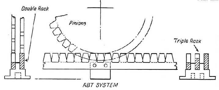
The ladder type of rack was not without defects, and in 1882 Mr. R. Abt patented an improved form of rack in which teeth were cut in the edges of narrow rectangular bars. These bars were placed in pairs, teeth uppermost, on chairs bolted to the sleepers. The teeth of the rack-
THE SNOWDON MOUNTAIN RAILWAY in Wales employs the “Abt” system illustrated here. This type of rack rail, patented in 1882, has teeth cut in the edges of narrow rectangular bars which are fitted in pairs to the sleepers so that the teeth of one rack are opposite the indents of the other.
The first line to use the Abt system was built in 1884 at Blankenberg, in the Harz Mountains. In 1894-
A type of Swiss-
The two leading axles are coupled by rods, and on each is a double pinion, gearing with the rack. It is, of course, the axle pinions that transmit the power -
The engine resembles the Riggenbach locomotive, since it pushes its train up the mountain side. There are no couplings, and three forms of brake are available. These comprise brake blocks that grip the drums on the driving axles, an automatic steam brake acting on two of the drums when the speed exceeds five miles an hour, and the use of compressed air in the cylinders as on the Riggenbach engine. The last-
The boiler of the engine is inclined at an angle of 1 in 11 to obtain a comparatively level surface to the water on steep gradients. The pressure is 200 lb per sq in. The side water tanks carry 440 gallons, and the coal bunker 10 cwt of fuel. The engine, which weighs in working order 17 tons 4¼ cwt, can propel a load of 18.5 tons at four to five miles an hour.
Another rack system was used on the railway up Mount Pilatus, near Lucerne, Switzerland. The Pilatus line, constructed in 1886-
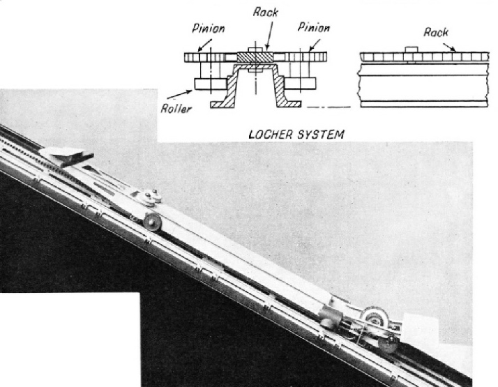
THE LOCHER RACK is employed to take the railway up inclines of 1 in 2 on Mount Pilatus in Switzerland. The car is prevented from leaving the track by a central guide which carries the double-
The under frame of the car is carried on four wheels. These are not power-
Another pair of similar wheels at the front end of the frame is used to guide the car and to work the automatic brake. The pinion wheels at the lower end of the car are driven by two horizontal cylinders through a crankshaft and gearing. The boiler is of the locomotive type, placed across the frame, and works at a pressure of 176 lb per sq in. The brakes that control the descending car are a hand brake on one of the engine cranks, a cylinder air brake as on the Abt locomotives, and an automatic brake that acts on a drum. The drum is connected with the front pair of toothed wheels by worm gearing. This brake comes into operation automatically should the speed exceed three miles an hour, and can also be applied by the brakeman on the front of the car. As an additional safeguard the car is fitted with clips embracing the running rails, to guard against derailment by wind. The car weighs 10½ tons in working order, and carries 176 gallons of water and 2½ cwt of coal. The normal speed of the car is two and a quarter miles an hour.
Another method enabling engines to climb mountainous railways is the “Fell” system, which is widely used for this purpose in many parts of the world. This method of increasing the adhesion of locomotives by means of a central rail was proposed by Mr. J. B. Fell during the construction of the Mont Cenis Tunnel. Patents for the special locomotives were granted to Mr. Fell in 1863-
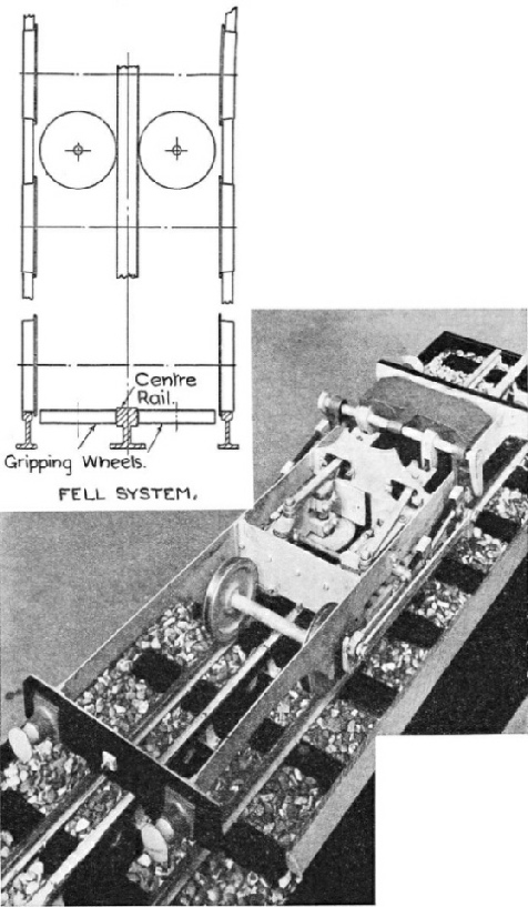 This railway was laid along the public road for a distance of forty-
A model of a “Fell” engine built for the Mont Cenis line may be seen in the Science Museum, South Kensington. The engine was carried on four-
ADDITIONAL ADHESION for locomotives when climbing steep gradients is given on the Fell system by means of a centre rail gripped on either side by horizontally placed wheels. This system was first used on a line laid over the Mont Cenis Pass and opened in 1868.
The additional adhesion was obtained by means of a central rail laid on all gradients steeper than 1 in 25. The central rail was gripped on either side by a pair of 2 ft 4 in wheels, pressed inwards by springs and levers, operated by screw gear from the footplate. Each pair of vertical shafts was held in a sliding frame between two transverse stays placed near the middle of the engine. At the upper ends of the shafts were overhung cranks, and the gripping wheels were fixed to the lower ends. The shafts on either side of the central rail were coupled by rods at the top and bottom, and were driven direct from the engine cylinders.
The motion of the crossheads was communicated to the carrying wheels through rocking shafts, levers, and outside connecting rods. The boiler pressure was 120 lb per sq in and the weight of the engine, in working order, about 20 tons. The pressure of the wheels against the centre rail was also some 20 tons, thus doubling the adhesion. The engine was capable of hauling a load of 20 tons up a gradient of 1 in 12 at a speed of ten miles an hour. The central rail was double-
Braking was effected by blocks acting on the carrying wheels and also by means of slipper blocks that gripped the central rail.
The Fell system is used on the famous Rimutaka incline on the North Island of New Zealand, and the picture on page 260 gives a fine impression of five Fell engines climbing the gradient. A full description of the New Zealand fell engines is given on page 261.
In another system, invented by the famous Swiss engineer Wetli, additional rails were laid between the track rails in the form of inverted V’s, with the apexes pointing up the incline. A double helix on a drum beneath the engine, driven by the cylinders, engaged with the V's and so propelled the locomotive forward. The helix may be regarded as a raised V round the drum.
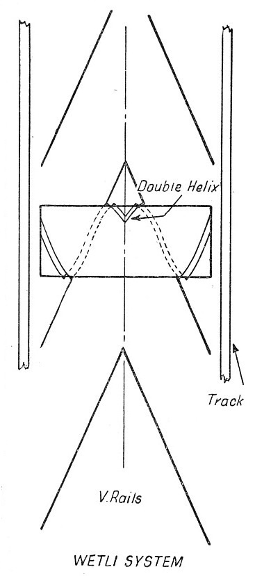 The Wetli system has not been used in practice chiefly because of the difficulty of laying the V’s sufficiently accurately to ensure smooth working. In addition, it was not suitable for use on small-
Rack engines have been improved in detail of design since they were first evolved, particularly when electric traction is employed, but the working principles of the various systems have remained unchanged.
Rack railways, employing one or other of the foregoing systems, operate in all parts of the world.
THE WETLI SYSTEM. In this system additional V-
Many of the most spectacular rack railways are to be found in Switzerland, and are used mainly for tourist traffic. A number of these lines, in addition to the railway referred to earlier, are operated on the Riggenbach system. These include the Rorschach-
In contrast with the Swiss rack railways is the Riggenbach rack section of 1 in 16 between Lengue and São Pedro on the Benguella Railway in Africa.
The Abt system is also used extensively in Switzerland, notably on the Brienz-
The rack rail is an ingenious device for overcoming the difficulties encountered by railway engineers in mountainous country, but high speeds are naturally out of the question. Even on the relatively speedy Visp-
You can read more on “The Conquest of the Clouds”, “The First Mountain Railway” and “Wonderful Alpine Ascents” on this website.