
© Railway Wonders of the World 2012-


Ruling the Traffic Routes
Controlling Speed and Direction of Trains by Electricity
THE MAGIC OF MODERN SIGNALS -
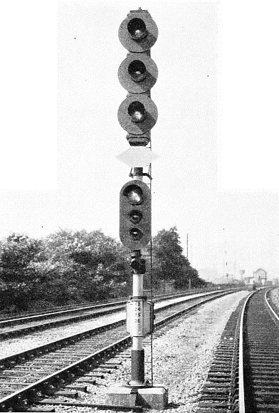
WONDERFULLY COMPACT is this modern signal on the LMS main line near Mirfield, Yorks. At the top are three searchlight lenses; each can show red, yellow or green. Under these is a division board denoting a lower group of signals which apply to the junction farther down the track.
SIGNALS, as we have mentioned in the chapter “The Magic of Modern Signals”, not only give the driver permission to proceed, but they also indicate either the route or the speed at which he may travel.
It is usual on British railways to have two signals at a junction. These signals are placed on bracket posts, one post 30 in higher than the other. When the upper signal is at “clear” it indicates that the route is set for the main line and that the driver may proceed along that route at a high speed. If the lower signal is “clear” it means that the points are set for the branch line, and that the train will be deviated from the straight; hence the engine driver knows that he must reduce his speed to negotiate the junction with safety. This method of indicating the direction in which the points are set is known as “route signalling”.
A modern development which has met with great success in the USA and which is now being tried out in this country at Mirfield, Yorkshire, on the LMS, is “speed-
The application of the multiple electric colour-
There are two main types of colour-
Both of these types of signals have their own backgrounds, consisting of a sheet metal disk about 30 in. in diameter, The signal head is mounted on a steel tubular mast, which, in addition to carrying the main signal, also carries auxiliary signals, such as those used for shunting or to distinguish this type of signal from other types to be met with on the route. In addition, a white enamel plate with a circle in it is sometimes mounted on the same post. This tells the engine driver that there is a telephone at that signal, and should he be held there for any unduly long period, it is his responsibility to ring up the cabin and see if he can pass this signal at danger.
But if a white enamel diamond-
With multiple colour-
The diagram on the panel indicates by means of lights the exact position of any train within the signalman’s control. All signals and points are repeated by miniature lights on the panel. The remote points and all signals are operated by turning thumb switches on the panel, while the points adjacent to the cabin are worked by levers.
The turn of a small switch by thumb and finger now achieves the same result that formerly required both hands and the whole weight of the signalman's body. The interlocking between signals and points is carried out electrically, so that should a switch be turned in incorrect sequence, no signal lighting or point movements can result.
Among the most interesting types of signals in this country are those which are being successfully operated by the LMS Railway at Mirfield, Yorkshire, a strategic point in the flow of traffic between the big industrial areas of Lancashire and Yorkshire.

AN ILLUMINATED TRACK DIAGRAM working in conjunction with the points and signals, is seen in this cabin at Hornchurch on the LMS Railway. The longer levers work the points in the vicinity of the cabin. The shorter levers operate the switches of the colour-
Coloured, electrically-
As a contrast to a busily-
The Track Circuit
An important feature in all signalling is the track circuit, which consists of a length of railway line insulated from its adjacent lengths and supplied with electrical energy to indicate to the signalman whenever a train moves on to it. Track circuiting is the basis for successful and safe working of long-
The resistance offered by a steel rail carried in and on a cast-

A MODERN SIGNAL BOX at Thirsk, on the route of the “Flying Scotsman”. Fitted with the most up-
All rail joints (other than those which are insulated) are bonded -
If a rail should break, or if a piece of metal should fall across the rails, the track would operate in exactly the same way as if a train were occupying the rails.
In certain instances where it is desired that the track circuit locking shall function only for a predetermined period, time element relays are used. A disk is made to rotate by magnetic means, thus loading a spring which can be adjusted to cause any desired cessation, or flow of electrical current for a period of from 1 to 60 seconds.
Track circuits are also utilized for approach-
Point mechanisms unless worked by hand are usually operated by electricity, but with some types the power is sup plied by compressed air, which moves a piston in or out of a cylinder as required. In these machines the point throw-
Numbers of these air-
Railway goods yards of this type are located in a central position, and are designed for the reception of goods-

THE CONTROL PANEL. This illuminated control panel at Sessay Wood, on the LNER, is provided with thumb-
Originally, these yards were arranged to be level, the wagons being shunted into the various sidings by means of a locomotive; but it has been proved advantageous, with the large yards, to provide a so-
At Banbury and Rogerstone on the GWR, and at Mottram on the LNER, the speed of the wagons as they run into the sidings is controlled by brakesmen, who run with the wagons for a short distance and set the brakes to such a position as to bring the wagons to rest at the required distance in the siding.
Owing to the steepness of the inclines in some yards designed to speed up the working, it is found necessary to replace brakesmen by means of “car retarders”, which are devices designed to grip the flanges of a wagon as it passes through, thus retarding it to the required speed. A yard of this nature is Whitemoor, on the LNER.
In modern practice, as at Banbury, the points continuously branch until they become sidings. By this method the points may also be more easily grouped in the neighbourhood of the control cabin.
Of the 19 sidings provided at Banbury, 10 are reached over five points, 7 over four, and 2 over three points. Each pair of points is provided with a point mechanism, and control valves for the supply of compressed air to the operating cylinders, which move the point blades. Each point is protected by an electric track circuit, which ensures that the points are correctly set.
In the signal-
At Banbury the control panel is designed for either automatic or independent-

SORTING GOODS WAGONS is simplified by this control panel in the signal cabin at the Banbury sidings, in Oxfordshire. The pressing of a button changes the points so that a wagon shunted past the control cabin is automatically run into its correct siding.
The push buttons for automatic working are fitted with an electric lock. When the push button is pressed in it is locked in the depressed position until the electric lock is released, either by the first track circuit being occupied, or by the “cancel” button being pressed. The buttons are mechanically interlocked so that no two can be simultaneously depressed.
Controlling the Points
An alternative method of operating the points is provided by means of a series of single-
The shifting of points to transfer a train from one line to another can be carried out entirely by electricity. Electric switchgear sets in motion the motor which moves the tapered rail ends or “point blades” as required, locking them in place to guard against derailment of the train when passing over the points. In addition to this, electric contacts are made which ensure that the indications given by the signals shall be in correct relationship to the route set by the rails.
The point mechanism comprises a self-
This machine can unlock the points, reverse them. and lock them again in two to three and a half seconds.
The casing of the mechanism is provided with a waterproof cover which can be locked if required. The electric motor, which is bolted to the mechanism box, is also in a watertight case with a locked cover, so that it can work in all weathers.

BANBURY HUMP YARDS are among the largest in England. This photograph was taken outside the control cabin, which is situated beside the line shown in the foreground. Opposite the cabin is the hump -
COMPRESSED AIR works these points, which are controlled by the electrical apparatus seen on top of the fence in the background. The top rail of this fence is the air pipe-
The motor, through a friction clutch (similar to that on a motor car) and a bevel pinion, drives a large bevel wheel, on the underside of which is a small cog-
This bar projects from the end of the mechanism case opposite the motor, and its function is to lock the points in position when they have been moved. The point movement is made by means of a “point throw-
The action of this roller resembles that of a key in a lock, the point throw-
In order to shift the points, therefore, a switch in the distant signal box is turned, the motor then moving the lock-
The final duty of the point machine is to report to the signalman that the points have been moved as required, and that they have been duly locked safely in their new position. This is done by “point detectors” -
 In the improvement of signalling by new methods there is one great difficulty which is not generally realized, but which is of the utmost importance. The problem lies in the installing of new and different indicators on a route without some risk of confusion to drivers long familiar with the old signals. This difficulty is one of the most important factors governing the rate at which old signal systems are being replaced by new. Obviously it is essential that any new method should be capable of working in conjunction with the other system during the necessary transition period.
MODERN POINT MECHANISM. The electric point machine illustrated left comprises: (A) the electric motor; (B) large bevel wheel with crank for hand operation; (C) main gearwheel; (D) point throw-
There are so many different improvements in signalling that it is impossible to indicate them all, but enough has been said to disclose the thoroughness of the search for better methods. It goes on, ceaselessly, in every branch of the complex system. Even the simple semaphore indicator has been radically improved, since the newer ones do not drop at an angle, to indicate “Clear”, but they move upwards instead of downwards from tile horizontal.
Guarding Against Failure
The reason is a good one -
The positions of the ordinary semaphore arm are given at night by “spectacles”, which are attached to the arm and pass in front of a lamp, a red light denoting “Danger”, a green “Clear”. Thus day and night signals depend upon visibility.
An ingenious method of ensuring that signals at “Danger” shall not be passed by a driver is in operation on the Great Western Railway between Paddington and Reading.
This system gives to the engine driver in the cab of the locomotive audible signals, corresponding to the position of the distant signals. When the distant signal is at the “all right” position a bell rings, and when the distant signal is at “caution” a siren sounds and at the same time the brakes are automatically applied. The application of the brakes and the sounding of the siren continue until the engine driver “acknowledges” the signal by lifting a small handle on the apparatus in the engine cab.

THE POINT MACHINE in service. The mechanism is shown complete with its locked covers bolted to the sleepers alongside the track. The various attachments to the blades and locking devices are clearly indicated.
On main lines carrying express traffic the colour-
All modern signalling aims at greater safety, and at the elimination of possible error. This tendency is clear if we recall the main trend of development -
You can read more on “Automatic Safety”, “The Magic of Modern Signals” and “Railway Signalling” on this website.