A Modern Steel Process that Facilitates repairs and Construction
CIVIL ENGINEERING - 10

22,000 FT OF WELDING - a two years’ task - carried out on the reconstruction of the Sharnbrook Viaduct, provides a good example of the importance of welding in the service of the railway. The recently strengthened viaduct carries the tracks of the LMS main line between St Pancras and the north over the River Ouse, a quarter of a mile south of Sharnbrook Station, Bedfordshire.
AMONG modern metallurgical developments the welding of steel is increasingly claiming the attention of railway engineers. In maintenance work the use of welding is becoming common in effecting repairs and building up worn parts, and it is also being pressed into service in the fabrication of steel structures and in building rolling stock. Its chief advantages in the latter connexion are that riveting is dispensed with and weight is reduced. Weight reduction in the rolling stock realm is, of course, of primary importance, as the lighter the train the less the power required for its propulsion. Several of the latest high-speed trains in America and elsewhere are composed entirely of all-welded rolling stock, and by careful design their weight has been reduced in this way by one-third as compared with previous standard vehicles of the same dimensions.
In Great Britain the most commonly-observed application of welding is to the track. In the vicinity of stations travellers may often see the intense blue-white flame of electrical welding apparatus in use, and they may notice that the workmen in charge of it are applying the flame to the rails at the point where two tracks cross.
Here, because a flange-way must be left through which the downward-projecting flanges of the wheels may pass, the wheels have, in effect, to cross gaps in the surface of the rails over which they are running. The presence of these gaps in the continuity of the rails causes the rails at the crossings to be subjected to a severe hammering as the wheels pound over them.
Where tracks cross one another at right angles, or nearly so, the wheels must pass over a clear gap in the rails 1¾ in in width, or thereabouts. But right-angled crossings are infrequent, and most crossings are at a very acute angle. Owing to the width of the wheel-tyre, therefore, and to the fact that the flange-way gap runs diagonally across the rail, there is no part of the average crossing at which some part, at least, of the tyre is not supported. Nevertheless, the shocks sustained by the rails are considerable, as is apparent even to the traveller in the trains, and rails wear away with exceptional rapidity. In particular, the fine point, or “nose”, to which the converging running rails are brought together wears down, as well as the two angles of the outer or “wing” rails of the crossing on to which the wheels pass from the point at what is known as the “knuckle”.
In earlier days, when the point of the crossing had thus become depressed and the wing rails deeply grooved, there was no alternative to taking up the whole crossing and substituting another, or at least to replacing all the four rails. This was a costly business. Now, however, welding, which can be carried out a number of times in succession on the same crossing, defers indefinitely such replacements. A portable apparatus, self-contained, is brought to the site, with its own motor-driven dynamo producing the necessary current. This is first used to grind away the worn rails to a perfectly smooth surface; then, by passing current through suitable electrodes on to the worn surfaces, metal is built on to them until the original profile of the rails is restored.

20-TONS WELDED MINERAL WAGON built for the LNER. The length over headstocks is 21 ft 5⅝-in; width inside body, 7 ft 11⅝-in; and height inside body, 4 ft 9½-in. The wagon’s cubic capacity is 820 cub ft, and its tare weight 7 tons 19 cwt. One advantage of the use of welding in the construction of rolling stock is the reduction of weight.
It is now the custom to build on to the rails alloy steels considerably harder in quality than the steel of which the rail was originally composed, so that the welded rail surface is thus of a better wearing quality than the rail was before welding. The process is not entirely without risk, as great care has to be taken that in the violence of the heat treatment so applied the rail is not made brittle.
In America welding is used also to build up the ends of the rails at the joints. Axle-loads on American railways are so enormously heavy that the rails get badly “battered”, or worn down, at the joints, and certain railways have now created a travelling organization of men who go round building up these joints with welding apparatus. This, of course, is a vastly bigger job than merely building up worn crossings, for whereas it is possible to travel for several miles without passing over a single crossing, there is a joint in each rail at 33 ft or 39 ft intervals on American tracks.
This brings us to another application of welding in the track which to a large extent does away with rail-joints altogether. It is becoming increasingly the practice on Continental railways to weld rails together in long, continuous lengths. The risk in so doing, of course, is that expansion may buckle the track out of shape on a hot day; but this is guarded against as carefully as possible by laying the long rails in warm weather, so that any movement that takes place is one of contraction rather
than of expansion.
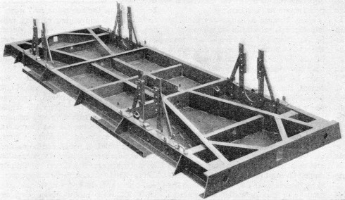
THE UNDERFRAME of an all-welded wagon built for the LNER. This picture clearly shows the large number of welded joints in a typical wagon.
In Germany rails of a standard length of 30 metres (98 ft 5 in) are now produced as a regular practice in the rail-mills, but considerably longer lengths than this have been welded together for use on bridges and in tunnels. The greater the extent to which rail-joints can be done away with, the smoother is the riding of the trains and the less the wear and tear of rolling stock. But this is only one advantage. Joints are the most costly part of the track to maintain, always needing more constant packing up and general attention than the remainder. In tunnels this is particularly so, and here, because of the confined space, the darkness, and the difficult conditions generally, rail-joints are the most troublesome. On the other hand, the temperature inside a tunnel is nearly uniform, so that no danger need be apprehended from expansion if long stretches of rail are welded together in continuous lengths.
The most remarkable experiment of this description that has yet been performed has been in Germany. In the Brandleite Tunnel, on the main line between Berlin and Stuttgart, which is nearly two miles long, the rails of the double track have been welded into four continuous lengths, each 2,640 metres, or 8,662 ft long. Even starting with 30-metre rails, the problem of welding on this scale was one of enormous difficulty. To make up 2,640 metres, eighty-seven welds in each run of rails would be needed, and if this had all to be done in the tunnel, with bad atmospheric conditions, the task would have been intolerable.
It was therefore decided first of all to weld the 30-metre rails into triplets, 90 metres, or 295 ft long, at the Neutiedendorf depot, several miles away, where “flash-butt” welding could be applied. This is welding by bringing the two ends close together, passing a heavy current through them, which “arcs” across the minute gap, thus creating tremendous heat, and then bringing the ends finally together to a firm adherence. But the question arose as to how rails 295 ft in length were to be transported from the depot to the tunnel, over 1 in 50 gradients, and round curves having a radius as sharp as 15 chains.
The problem was solved successfully by loading them on sets of six bogie wagons, twenty-four rails at a time, leaving about ¾-in between each pair of rails, to allow freedom of movement of each one relatively to its neighbour as the curves were traversed. When this remarkable train-load was in progress, all traffic on the adjacent line was stopped. Because of the careful precautions taken, however, no difficulties were experienced, and it was found possible to work the rail-train round the sharpest curves, and over cross-over lines, without the slightest suspicion of trouble. The snake-like appearance of the loads in such conditions was remarkable.
In this way, therefore, 288 of the welds were made in comfortable and convenient conditions at the Neutiedendorf depot, and it was only necessary to make sixty welds, fifteen in each run of rail, in the tunnel. As flash-butt welding requires special apparatus, which could not be used in the tunnel, it was necessary to make the final welds in the tunnel by the “thermit” welding process. At the two ends of the Brandleite Tunnel, where slight variations of temperature may be looked for, the 8,662 ft of the continuous rails is flanked by about 650 ft of ordinary rails, jointed in the usual way.
Application to Bridges
Another application of welding which is being applied on a constantly increasing scale is to bridges. There are numerous railway bridges in which the various plates and rolled sections used in building up the girders have been united, not by riveting, but by welding. One great advantage of this welded construction is that all the drilling of rivet-holes - which is not merely a lengthy and costly business, but also weakens the steel - is avoided.
The same principle is applied also in bridge repairing. An outstanding example of this treatment on a large scale is found in the work which was carried out recently by the LMS Railway on a viaduct which carries the main line of the Midland Division across the River Ouse just south of Sharnbrook Station, seven miles north of Bedford. The viaduct is of wrought iron girder construction, carried on substantial brick piers It consists of three 60-ft skew spans across the river, flanked by four 56-ft square spans at the south end, and by three 56-ft square spans at the north end, the whole carried at about 35 ft above
ground.
Each span consists of six girders; under each rail there is a wrought iron girder 5 ft 6-in deep, with lattice girders on the outside to carry the parapets. Between these longitudinal girders there are several rows of cross-bracings connecting them together in a solid framework. The track itself is carried by cross-timbers of 12-in by 6-in section, 30 ft wide, extending
across the width of the bridge.

AFTER WELDING. This illustration shows a wing rail being brought to the correct profile after electric-arc welding. This final surface is produced by grinding with a carborundum wheel that is operated through a flexible shaft - seen to the operator’s left - by an electric motor.
As the bridge is in the middle of the well-known Sharnbrook bank, which for three miles has a gradient of 1 in 120, expresses travelling towards London cross it at a speed which is generally well above seventy miles an hour. The vibration caused the rivets in the cross-bracings periodically to work loose and to require renewal; while the girder bearings had also worked their way into the bedstones on which they were supported, to a depth varying from ½-in to ¾-in which caused further undesirable oscillations of the structure as the traffic passed over it.
It was therefore decided thoroughly to repair and strengthen the viaduct. Among other changes were the substitution of steel floor-plates ⅝-in thick for the transverse timbers, and the provision of a new floor. Further, to reduce the amount of work which would have been required on the site in drilling the floor-plates and cutting out rivets, the new connexions were to be made by welding instead of riveting.
A special welding plant of the “Quasi-Arc” type was brought to the site, comprising two machines, each consisting of a Dorman petrol engine of 33 brake horse-power, driving a welding dynamo and auxiliary dynamo at 1,500 revolutions a minute. The welding dynamo was a compound-wound direct current machine capable of delivering a maximum current of 308 amperes for one hour, or 246 amperes indefinitely, the voltage remaining constant at 50 volts. By the use of three reactances, each dynamo was arranged to supply current to three welders simultaneously, and each operator was supplied with a resistance regulator, by which he could adjust the current to suit the particular size and type of electrode that he had in use. The total amount of welding, mostly double run, amounted to 22,000 feet over the whole length of the viaduct, and no fewer than 66,400 electrodes, each 18 inches long, were used up before the work was completed. The auxiliary dynamo, another compound-wound direct current machine, supplied current at 220 volts, and was capable of delivering 23 amperes continuously.
A Two Years’ Task
It has to be appreciated that the whole of the work work was carried out without any interruption to traffic, except on four Sundays, when the passenger trains were temporarily diverted to the adjacent goods lines. This diversion was necessary when the girders were lifted three inches vertically off their worn bedstones, so that new steel bearing plates, one inch thick, might be inserted between the girders and their original beds, and the worn spaces in the bedstones filled up. The girders were then lowered again into position. As six pairs of girder-ends required lifting in each span, this alone was a big operation, and provided plenty of work for the ten hydraulic jacks until the whole of the ten spans had thus been dealt with. Yet this complex operation was completed in no more than four Sundays in all.
Of the new steel floor-plates 140 tons in all were needed. Two seven-ton steam cranes did the work of dropping the floor-plates in position, and removing the old transverse timbers. This also, of course, required “complete possession” of the lines, and diversion of the traffic to the goods lines, as it was necessary to dismantle the track while the timbers were removed.
The average time taken to complete the work on each span was about four weeks. Careful observation was taken to see that no leakage of water was taking place through the floor-plate joints, and that the whole floor was thoroughly water-tight; after that it was possible to unload the ballast on the new floor, to take the track off its temporary supports, and to lay it on ballast-supported sleepers in the ordinary way.
The whole of the operation, which took two years to complete, reflects great credit on the engineering staff responsible for the smoothness with which it was carried out.
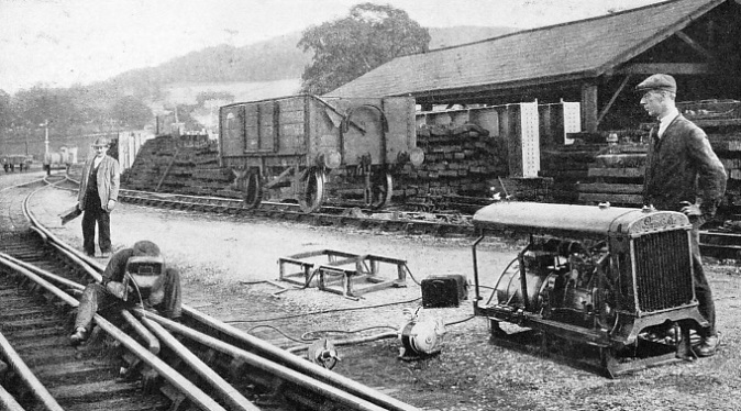
A QUASI-ARC PLANT in operation near Bathampton, Somerset. These plants can be easily transported. The welding depends upon the intense heat of the electric arc - about 3,500 degrees centigrade - which causes the simultaneous fusing of a portion of the rail and of a flux-covered wire rod, or “electrode”. The operator is engaged in building up the worn nose of a crossing.
You can read more on “Engineering Equipment”, “The Permanent Way” and “Switches and Crossings” on this website.
You can read more on “The Craft of the Welder” in Wonders of World Engineering


