Systems of Automatic Train Control
THE MAGIC OF MODERN SIGNALS - 3
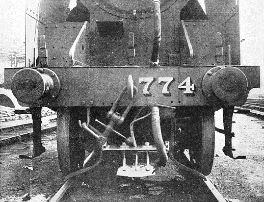
MAGNETIC INDUCTION between the train and signal apparatus is used in the Strowger-Hudd system. There is no direct contact between the train and the track apparatus, but the receiver on the engine—here seen below the buffer-beam—passes over magnetic inductors between the lines which give audible warning in the cab.
THE old saying, “familiarity breeds contempt”, might well be applied to the thousands of railway travellers who daily take their seats in the trains and are confident of a safe and speedy passage. Praiseworthy indeed are the untiring efforts of the railway engineers and staff who make it possible. Readers have already seen how Nature in her wildest moods can play havoc with a railway to the point of utter destruction; even when not totally destructive she can be capricious enough to dislocate train services and cause great delay and inconvenience. Probably everyone reading these words has made a train journey in a fog, which renders useless the finest system of visible signalling it is possible to have.
A blind man finds his way about by the senses of touch and hearing. An engine driver who cannot see beyond the chimney of his locomotive, and to whom, therefore, the wayside signals are invisible, has to rely on his ears. Thus in the early days it was soon realized that some sort of sound signal would have to take the place of visible signals in foggy weather. The well-known “fog signal”, or detonator, is the result.
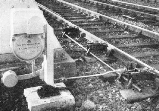
AN AUTOMATIC MACHINE which places a series of fog signals on the line. The detonators are exploded by the engine wheels and so give warning. The machine can be worked from an adjacent signal cabin or by a special “fogman” along the permanent way.
The “bang” portion of the modern version is a flat metal case about the size of a five-shilling piece, containing three fulminate caps which explode a charge of gunpowder when crushed by the engine wheel. There are two kinds: one has leaden clips for attaching to the top of the rail by hand; the other has a specially shaped metal base which enables it to be placed on the rails, when a signal is at “danger”, by an automatic machine which holds a supply of fog-signals. This somewhat resembles the penny-in-the-slot sweetmeat and cigarette machines seen on the station platforms and elsewhere. The railwaymen term these machines “deaf-and-dumb fogmen”. They can be put into operation from a signal box, or worked by a fogman from any convenient point.
Fogmen usually belong to the permanent way department, and are normally employed as platelayers, and so on. On some lines signalmen have to note a certain object some little distance from the signal-box - a signal post, telegraph pole, or even a post placed especially for the purpose. All the time this is clearly visible, everything proceeds as usual but as soon as mist, fog, or falling snow obscures the “landmark”, the signalman gives warning by bell or telephone, and the fogmen are called out. They take up a position near the “distant” signals, and place detonators on the tracks all the time the signals are at “caution”, removing them as soon as the signal indicates “clear”. To avoid any possibility of error, a set of miniature signals is often placed at the position occupied by the fogman (called a fog post); these are directly connected to the full-sized signals so that they operate with them and give the same indications. So long as the driver hears no sound, he can proceed with safety; but as soon as a bang is heard under the leading wheel of the engine, he knows that the signals are against him, and acts accordingly.
Fog signalling is not a very pleasant job, as one may well imagine; but the companies do their best for the men, relieving them as often as possible, and providing fire-buckets (known as “devils”) and shelter huts to counteract the effects of the weather.
It has long been maintained, however, that a system including audible or visible signals in the engine cab would he far preferable to absolute reliance on the human element, especially if this could be supplemented with some sort of mechanical control, such as that already applied to the Underground electric lines. Several such systems have been devised and tried out. Automatic train control is becoming quite common in America. In England, the Great Western Railway has a very satisfactory system operating on some of its main lines; the Southern Railway also has carried out trials, but of another system. In both systems the aspect of the signal is given by audible warning; and, if it is at “danger”, the brakes are applied automatically. In this connexion it is worth noting how the trend of opinion has completely veered round regarding mechanical control. At one time automatic signalling was considered inferior to human control, the fear being that something might go wrong and cause an accident. Experience proved the fallacy of this reasoning; we know now that it is the human being that is frail, while the mechanical signalman never tires and never makes a mistake. There is a parallel example on the roads, where the point duty policeman is gradually being superseded by “stop-and-go lights”.
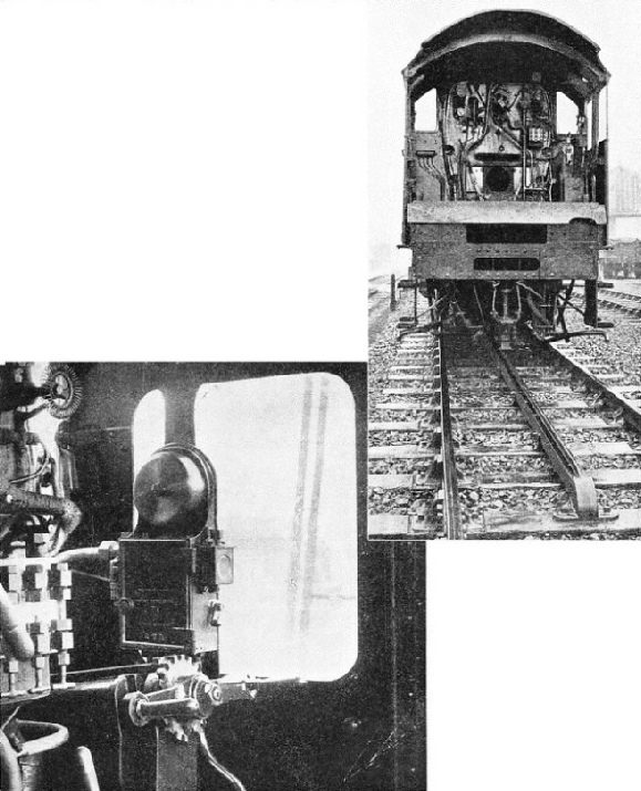
SHOWING THE SHOE on the engine in contact with the ramp that automatically actuates the audible signalling apparatus in the cab.
THE WARNING BELL in the cab of a Great Western Railway engine. When the distant signal is clear this is indicated by the bell ringing in the engine cab. If the signal is at danger, a siren sounds and the brakes are partly applied by the automatic train control apparatus. The engine driver thus knows the aspect of the signal, whatever the weather.
On the Great Western Railway, if the distant signal is “off” (clear) a bell rings in the engine cab. If it is “on” (warning or caution) a siren sounds and the brakes are partly applied; thus the engine driver knows exactly what aspect the signal is showing, even in the thickest fog. The indication is given about a quarter-mile before reaching the distant signal when this is on a separate post; but when - as often happens in suburban and other congested areas - the “distant” arm is placed under a “stop” arm on the same post, the indication is given at the post itself, in time for the driver to pull up at the next “stop” signal if the “distant” arm has shown that this is in “stop” position.
The apparatus is worked electrically by means of a ramp on the track and a contact shoe on the engine. The ramp consists of an inverted “T” bar of steel mounted on a baulk of timber and placed between the rails, so that the top is 3½ in above rail level. On straight lines the ramp is set slightly askew, being 1½ in off centre at either end; on curves it is placed 1½ in off centre, toward the outer rail. It is permanently fixed in position, and unlike electric fouling bars, treadles, point locks and other similar contrivances, does not move. The ramp can be electrified by current from a local battery, switched on through a relay operated by contacts on the lever in the signal-box, and on the distant signal itself. The current is on only when the signal shows “clear”; it will thus be seen that a broken wire, signal or battery failure, or mishap to the electrical apparatus, leaves the ramp “dead”; and a “dead” ramp cannot give the driver a “clear” signal.
The contact shoe on the engine is attached to the buffer beam, and has a vertical movement of 1 in, as it is adjusted to hang normally 2½ in above rail level. The ramp, being 3½ in high, lifts it the required amount. This lifting movement opens a switch. Inside the engine cab is a small case containing an electro-magnet with two windings and a floating armature which is connected to the brake valve and alarm siren; also a polarized relay, and a slow-release relay connected to the bell switch. The bell itself is mounted on top of the casing. There is, in addition, an automatic battery cut-out, which switches out the engine battery when the engine is at rest in sheds or sidings. For the information of non-technical readers, a “relay” is merely an electrically-operated switch, enabling current from a distant source to switch in a local battery; in the present instance, current from the ramp switches in the battery carried on the engine - a four-volt accumulator, which is usually of the nickel-iron type.
The action of the apparatus is as follows. When running normally, the contact shoe on the engine hangs at its lowest position, and the switch attached to it is closed. Current then flows from one pole of the battery on the engine through the switch, and through the upper windings of the electro-magnet (which is thus energized), returning through the metal-work of the engine to the other pole of the battery, which is connected to the engine frame. The electro-magnet, being energized, draws the armature up to it, depressing the lever at the other end, and keeping the vacuum brake valve tightly closed. The armature is prevented from sticking to the poles of the magnet by a row of brass pins, which keep armature and poles about 1/32 in apart. Brakes remain off, and, of course, no signal is heard by the driver.
The signalman, having received the “all clear” from the next box ahead, pulls off his home and starting signals; this releases the interlocks on the “distant” signal lever, which he then pulls over. This action closes the switch on the lever; the distant signal arm drops to “clear” position and completes the circuits. Current now flows from the battery in the signal-box via the lever switch to a relay in a box near the ramp. This relay immediately closes a switch connected to the ramp battery, which is located in the relay box; this switch is double-pole, one pole being connected to the ramp via the contact on the distant signal, and the other to the running rails; so that the ramp is now “alive”. The voltage is only about sixteen, so there is no fear of current leakage, or accidental shock to track workers.
Along comes the train; the contact shoe on the engine strikes the ramp and is lifted by it, opening the switch attached to the shoe, and cutting off the current from the engine battery to the electro-magnet; but this is not de-energized, as current from the ramp passes through the lower windings, retains the armature in its raised position, and keeps the brake valve closed. At the same time the ramp current passes through the relay in the casing, operates this and switches in the bell, which immediately rings. The bell is of the trembler type, made especially strong to withstand the vibration of the engine. The bell continues ringing for a few seconds, as the relay is of the slow-release type, and “hangs up” slightly after the engine has passed over the ramp. The action is very similar to an ordinary front-door bell-push with a stiff plunger which does not release immediately after it has been pressed.
The driver, hearing the bell, knows that the signal is showing “clear”, even if the weather is so foggy that he cannot see beyond the chimney; while in clear weather it eliminates any possible chance of a signal being misread, or even missed altogether.
Supposing, however, that the section ahead is occupied, and the signalman leaves the signal in the “on” position. The ramp remains “dead”. When therefore the contact shoe on the engine strikes it and opens the shoe switch, and current from the engine battery is cut off from the electro-magnet, there is no current from the “dead” ramp to take its place. Consequently the magnet is de-energized, and the armature falls away from the poles, and opens the brake valve. Air immediately rushes into the brake pipe through the siren, sounding the warning and partly applying the brakes. As there has been no current from the ramp to energize the bell relay, the bell remains silent. The engine-driver, in normal circumstances, immediately regains control by operating the resetting handle at the side of the magnet case; this pushes up the armature and closes the brake valve. The driver then shuts off steam, and prepares to stop at the home signal if this is at “danger” by the time the train reaches it. In the extremely unlikely event of anything happening to both driver and fireman, so that the train ran on unattended, the siren would continue to give its warning, and air would enter the train pipe until the vacuum was entirely destroyed and the brakes applied at full force, bringing the train safely to a standstill.
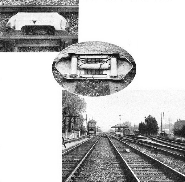
TRACK EQUIPMENT in the Strowger-Hudd system. Just before “distant” signal two inductors are placed 200 ft apart, while at “stop” signals they are combined as one unit. The first inductor is a permanent magnet ; the second inductor is an electro-magnet.
The above system is giving perfect satisfaction and is in daily operation on many miles of the Great Western Railway. Its use is being rapidly extended and will eventually be applied to the whole of the line. It has so far been found necessary to give audible warning at distant signals only; but the apparatus could, of course, be applied to all signals if needed, whether these are manually or electrically operated.
The Strowger-Hudd system of automatic train control, tested on the Southern and LMS, differs from the above in relying on magnetic induction between the train and the signals. There is no contact between the locomotive and the apparatus, and no electrical equipment is fitted to the locomotive. Warnings are given, when the distant signal is “on”, by a prolonged blast on a hooter in the engine cab, and by an application of brakes. If the signal is “off”, a short blast is given. At home signals no sound is heard if they are “off”, but if they are “on”, the distant warning is repeated and the brakes applied.
There are four principal parts composing the apparatus on the engine: the receiver, the train control valve, the acknowledging plunger, and the hooter. The track equipment consists of two “inductors” at each signal. These are similar to very short ramps, and at distant signals are placed about 200 ft apart, and a little in advance of the signal. At “stop” signals they are combined as one unit. The first inductor is a powerful permanent magnet throwing an intense magnetic force at right angles to the rails, being placed crosswise between them. The second inductor is an electro-magnet, which is “dead” when the signal is “on”, or at danger. When the signal shows “clear”, a switch on the signal itself cuts in a small battery and converts the “dead” inductor into a powerful electro-magnet throwing its force parallel to the rails.
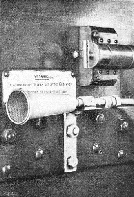
THE HOOTER in the cab of an engine fitted with the Strowger-Hudd apparatus. Warnings are given, when the distant signal is at danger, by a long blast. If the signal is “off” the hooter gives a short blast. At other signals no sound is heard if all is clear, but if they are at danger, a long blast is given and the brakes are applied.
The receiver on the front of the engine consists of four iron plates, mounted on a brass frame so that they can pass within four inches of the inductors; and connected to these plates are four pole pieces. Two of the plates are in line along the centre of the engine; the others are arranged one at either side. A centrally-pivoted “spider” armature is arranged so that it can be in contact either with the fore-and-aft pole pieces, or with the side ones. The former is the “normal” position, and in that position it keeps closed a “pilot valve” connected to the main train-control valve. All the time it is closed the brakes remain off.
When the engine passes over the first inductor (permanent magnet) the two side plates on the receiver are energized, and the pole pieces connected to them immediately attract the adjacent arms of the “spider” armature, causing it to move round a little and open the pilot valve. This admits air to the underside of a diaphragm piston in the main control valve, which opens in turn and admits air to the train pipe, starting the brake application; and, as the air has to pass through the hooter, this at once begins to sound. This action always takes place at a distant signal, whether off or on. If the signal is showing “all clear”, the switch attached to it will be closed, the battery switched in, and the electro-magnet forming the second inductor will be “alive” and energized. As this throws its magnetism parallel to the track, the fore-and-aft plates of the receiver will now be energized as the engine passes over the inductor, and the pole pieces connected to them will pull the armature back, closing the pilot valve. This in turn shuts the main control valve and stops the hooter from sounding. Thus the short blast of the hooter, given while the train was travelling between the two inductors, indicates “all clear” to the driver; the amount of air admitted to the train pipe through the hooter has very little effect on the brakes, and is at once removed by the ejector or vacuum pump.
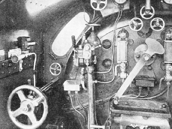
THE POSITION of the Strowger-Hudd apparatus in the engine cab. The hooter is placed in front of the driver at the side of the cab above the reversing wheel seen at the bottom left-hand corner of the picture.
Supposing, however, that the distant signal remains at “danger”, it does not switch in the battery, so that the second inductor remains “dead”; consequently the hooter continues to blow, and the brakes will be fully applied unless the driver presses the acknowledging plunger knob, which returns the armature to its original position and closes the pilot valve. He then shuts off steam and applies the brakes with his own valve in the usual manner.
At a stop signal, the inductors being combined, no audible warning is given if the signal is off. The signal switch being closed, the electro-magnet is energized as well as the permanent magnet; and, as all four collecting plates receive equal magnetic impulses, the armature does not move and the pilot valve remains closed. If two children’s toy magnets were placed on a table, end to end, say ¼ in apart, and a needle placed midway between them, the needle would not move to either of them; the effect mentioned above is the same. If, however, the signal is on, the electro-magnet remains “dead”; the permanent magnet then energizes the side plates as the engine passes over it, the armature moves, opens the pilot valve, blows the hooter, and applies the brakes as before. If the driver does not press the acknowledging plunger and take control himself, the train will stop of its own accord. The acknowledging plunger is, therefore, equivalent to the “dead man’s handle” of an electric train.
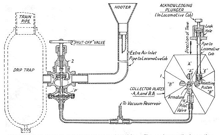
THE STROWGER-HUDD AUTOMATIC TRAIN CONTROL. The receiver on the locomotive comprises collector-plates AA and BB, arranged as shown at 1. These plates pass over the magnet fixed between the rails, and are energized by its magnetism, thus controlling the pilot valve X, by means of the armature Z. In the locomotive cab is the train control valve, 2, with the diaphragm P, which normally keeps the valve G closed against the suction of the train pipe. When the pilot valve X allows air to press on the underside of diaphragm P, valve G is lifted and air is sucked in through the hooter, thus giving warning and applying the brakes.
As with the siren and bell device, trains can be operated with safety by means of this system of control in the thickest of fogs. Even in clear weather the audible warnings are a great aid to the engine-driver, especially at awkward places on the line where signals “want some finding”, as the enginemen say; or when clouds of steam and smoke from the modern short chimneys blow across the cab windows and obscure the outlook, just when the driver wants them clear.
You can read more on “The Magic of Modern Signals”, “Stopping the Train” and
“The Vacuum Automatic Brake” on this website.


