© Railway Wonders of the World 2012-


How a Locomotive is Built
A Giant of the Railway Takes Shape

THE FIREBOX BAY in the boiler shop of the locomotive works at Swindon. The flanging of the plates which form the firebox is carried out by hydraulic presses. One press at Swindon exerts a force of 650 tons. A smaller press exerts a force of 200 tons. After being pressed, the firebox plates are cut to shape by oxygen-
ONE hundred and fifty tons of engine and five hundred tons of train at more than a mile a minute -
Fortunately, British locomotive engineers have over one hundred years of experience behind them, and this fund of knowledge, combined with great developments in machine tools and metallurgy, has made it possible to evolve the wonderful engines of to-
The modern locomotive works comprises a surprising range of machinery, from the high-
Engine-
It will be more convenient, however, if we review the procedure at one of the largest works in England, the locomotive shops at Swindon, where are built the famous “King” class engines of the Great Western Railway.
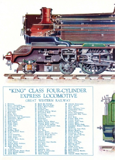
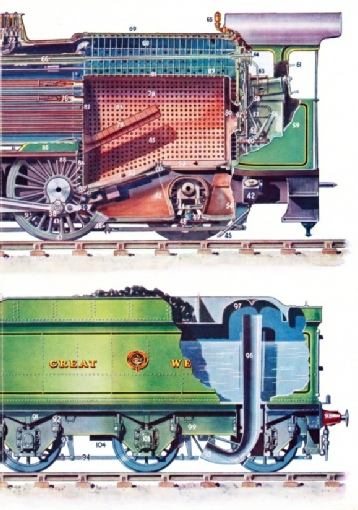
The colour plate accompanying the opening chapters of this work will prove an invaluable guide in identification of the various parts described.
We will consider first the real “heart” of the locomotive -
The cylinders of the “Kings”, with their attached steam chests, consist of three large castings. The largest of these comprises the two inside cylinders, with their valve chests, and the curved saddle which supports the smoke-
The cylinders are cast from specially selected iron, and the casting has to be absolutely free from defects. The iron is melted, together with a mixture of coke and limestone, in a cupola or vertical brick-

THE BOILER before it is covered with its insulating coat. To the left is the smoke-
The sides of the cylinder castings, together with the face of the smoke-
The steam chests are bored to receive the piston valve bushes in a special machine, which deals with all four of the inside cylinder bushes -
Cylinder bores and piston valve bushes are finished in a large grinding machine. A battery of machines is in operation for drilling and tapping the bolt-
The fitting of the piston-
The frames, forming the sides of the locomotive under-
Cutting by Flame
This preliminary cutting is done by means of a flame of coal gas, not unlike the familiar old-
This cutting jet of flame is held in a special machine with an arm overhanging the locomotive frame which is laid horizontally on trestles. Flexible pipes convey gas and oxygen to the jet. This movable arm carries, in addition to the jet, a small electric motor with a magnetized spindle. As this spindle revolves, it follows the edge of a small steel pattern or template, so that the jet on the end of the arm is made to travel in a similar but longer path. It will be seen, then, that by using a small template in thin sheet steel a large locomotive frame can be cut by the oxy-
The axle-
The crank axle on to which the inside cylinders drive is built up from bars and slabs of steel. The slabs are machined and bored for the bars on to which they are shrunk, the assembly being turned in a lathe to form the crank pins and shaft.
The wheels are of cast steel, bored to receive the axle ends, which are forced in hydraulically at a pressure of about 130 tons. The steel tyres are bored rather smaller than the diameter of the wheel, and are shrunk on to the wheels. In this operation the tyres are heated in a gas furnace so that they expand, and on being placed over the wheels they are allowed to cool. When they contract, of course, the tyres grip the wheels tightly. As a further safeguard a retaining ring is hammered down between a lip on the tyre and the rim of the wheel itself. Next the wheels are finished to size on a special lathe. The holes for crank or coupling-
 Finally, the wheels are tested in a special balancing machine, so that necessary adjustments can be made to ensure absence of vibration even at speeds equivalent to sixty miles per hour on the track.
THE LOCOMOTIVE WORKS belonging to the Southern Railway at Eastleigh (Hampshire), seventy-
The “motion” is the moving mechanism which transmits the pressure of the steam to the driving wheels. The first item for consideration is the piston, which is forced backwards and forwards in the cylinder. The piston comprises a hollow iron circular box, provided with a pair of expanding rings similar to those fitted to petrol engines. The piston is screwed by a tapered thread to one end of the piston rod, which passes through a stuffing box and gland in the back cylinder cover. The stuffing box, as its name implies, is stuffed with flexible metallic packing and graphite paste, to ensure that no leakage of steam shall occur, while it permits the rod to slide freely to and fro.
Here it is necessary to digress a little on the working of the piston and its attendant mechanism. The end of the piston rod outside the cylinder is attached to the crosshead, a steel casting provided with “slippers” which move between two slide bars attached to a steel bracket at one end and the cylinder at the other. The connecting rod is pivoted on the crosshead at one end, the other extremity having a bearing on the crank-
The bogie is built up with side frames, axle-
The locomotive tender chassis is built with framing similar to that of the engine. Water tanks, composed of steel plates, are riveted in place on the undercarriage, and brake gear, water pick-
While the locomotive chassis has been under construction, the shops have been busy with the boiler. It is on the engine's steam generator that efficiency in service so largely depends. The boiler must be capable of raising steam quickly and in sufficient volume to supply the cylinders in all working conditions. Absolute safety in operation is, of course, essential, and provision must be made for cleaning at frequent intervals. In addition, the boiler must be so designed to conform to the limits of the space available on the engine chassis.
Similar methods of construction are employed by most of the boiler engineers in Britain; but as we are considering the building of a Great Western engine, the procedure adopted at Swindon Works will be followed through the various stages.
One of the main features of the GWR standard boiler is the coning or tapering of the barrel, so enabling the fullest use to be made of the intense heat at the firebox end. Another advantage lies in the relatively small space at the front end of the boiler, which prevents a forward surge of water with the attendant danger of uncovering the firebox crown plates.
The boiler comprises three main components, the firebox, the barrel, and the smoke-
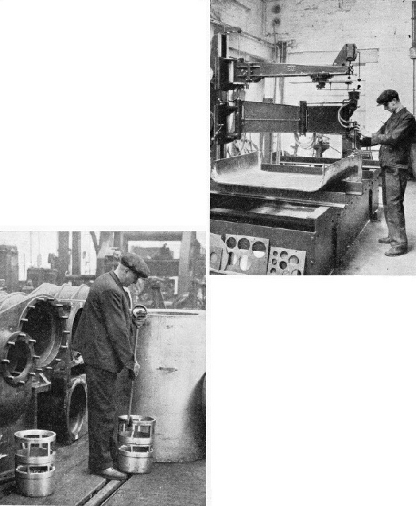
AN OXYGEN CUTTING-
THE “DRIKOLD” SHRINKING BATH.
Piston valve liners being fitted to the cylinder casting with the aid of the “Drikold” Shrinking Bath at the Swindon works of the Great Western Railway. Liners are ground too large for the housings, and are “shrunk” to the right size by a chemical freezing mixture. When in position the liners regain their normal size and thus fit tightly.
The barrel is built up from rolled steel plates. The front end is closed by a steel tube plate, drilled for the steel fire-
One of the most interesting processes in the building of a giant boiler for a modern locomotive is the shaping of the various plates that form the firebox.
The plates are flanged by means of great hydraulic presses that squeeze the metal over suitably shaped “dies”. These dies are of cast iron, accurately machined to the correct shape of the finished plates. The steel throat-
There are two hydraulic presses in the Swindon shops operating at the enormous pressure of 1,500 lb per square inch. The larger press exerts a pressure of 650 tons, the smaller a pressure of 200 tons.
This large press will finish a steel throat-
Boiler construction calls for rather more accurate workmanship than is generally supposed. Where a plate edge butts against another edge, the touching surfaces have to be carefully machined, and the fit of barrel plates one inside the other must be perfect.
The firebox wrapper plates and the barrel plates are rolled to shape in large bending rolls. The barrel plates are rolled conical throughout their length. The ends, however, have to be parallel, as the barrel rings fit one inside the other. To make the ends parallel a special press is used having a central block the same diameter as the inside of the barrel rings. Surrounding the centre block is a series of movable blocks, arranged spoke-

PREPARING A LOCOMOTIVE FOR THE ROAD at the Eastleigh works, which are the largest possessed by the Southern Railway. The picture shows a locomotive undergoing a general overhaul, which includes the application of fresh coats of paint and varnish.
The next stage is the assembly, on separate jigs, of the inner firebox and the outer casing. A few temporary bolts are used to hold the various plates together while the rivet holes are drilled in special machines. After drilling, the plates are riveted together -
The inner copper firebox is next placed inside the steel casing with the foundation ring in position. A few temporary bolts are used to hold the boxes in place for the next operation, the drilling and tapping of the stayholes. In a locomotive firebox there are hundreds of stays -
Firebox Safety
The stay holes are drilled through a template or jig, to secure accurate spacing and position. A portable machine is used for this work, and both steel outer shell and copper inner firebox are drilled through at the same time to ensure perfect alignment.
After the stays have been inserted the barrel is lined up with the firebox and held in place by temporary bolts for the final riveting to the throat-
The riveting is done in a powerful hydraulic machine with a gap 23 ft in length. For this operation the whole boiler is lifted by an overhead crane and lowered between the jaws of the riveter. The riveting rams are worked from the same platform as the crane thus ensuring complete control over the riveting. At the front end of the boiler the smoke-
Front and back tube plates are also joined by longitudinal steel stays. Finally the boiler is taken in hand by the boiler mounting department for the fitting of safety valves, superheater, water gauges, and other accessories.
The completed boiler is first tested under hydraulic pressure to some 40 lb per square inch above the working pressure, and then at working pressure under steam. The boiler is given a coat of anti-

RAISING AN EXPRESS PASSENGER ENGINE off its wheels for the purpose of an overhaul at the Southern Railway’s works at Eastleigh. All engines are withdrawn from service at regular intervals. Various parts of the locomotive have set periods for overhaul. The brake-
We have briefly reviewed the construction of the various components of a modern locomotive and now come to the erection of the engine. First the finished frame plates are placed on low trestles and the more important locating lines are marked out on both sides. These lines show the positions of the cylinders, inside motion plates, saddle casting, valve-
The frames are then lifted into a vertical position and mounted in adjustable forked stands. Cross-
The next operation is the fitting of the trailing “cheeks” of the leading “horns”. The horns are the slots in which the axle-
Inside cylinders and motion plate are now bolted temporarily in the frames. Their correct position is determined by a simple yet effective method. A cord or piano wire is passed through the bore of the cylinders, through the motion plate, and over a straight edge that coincides with an imaginary line between the centres of the leading horns. This ensures that the thrust of the pistons shall be delivered to the crankshaft at exactly the correct angle.
Valve gear and saddle castings are next tried in the frames, and holes for the carrying bolts are marked off. The castings are removed for drilling and are then temporarily bolted between the frames to ensure rigidity while the outside cylinders are fitted.
When the framework is practically complete, as much as possible of the “inside” gear is fitted before the boiler is lowered on to the frames.
Before final attachment to the undercarriage, the boiler is coated with a non-
Preparations are next made for adding the wheels, or “wheeling the engine” as it is called. Axle-
Coupling and connecting rods, valve and reversing gear are next fitted and the engine is ready for valve setting, an operation that may be compared with the valve timing of a motor-
All dirt and grease are finally removed from the engine ready for painting and varnishing. The bogie is run under the front of the locomotive and secured in position, after which the springs on all wheels are adjusted so that each carries its correct proportion of the engine’s weight.
After a short trial run, the engine is employed for a time on local trains, and is then put into service for the working of passenger expresses.
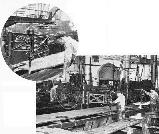
FRAME CUTTING. An oxy-
You can read more on “Halls of the Giants”, “How a Locomotive is Built -
“Locomotive Accessories” on this website.