
© Railway Wonders of the World 2012-


The Severn Tunnel
One of the Longest Under-

THE WELSH PORTAL of the Severn Tunnel is 4 miles 624 yards from the Gloucestershire entrance, and of this distance 2¼ miles are underneath the River Severn. The total length, including approaches, is approximately seven miles.
THE River Severn has always formed, at its mouth, a serious obstacle to through traffic between South Wales and Bristol and the south-
Until quite modern times the crossing of the Severn estuary had to be made by boat, and the passage was, to a greater or less extent, dependent on the state of the tide. Apart from craft of all kinds that followed no regular course, three established ferries are known to have existed. There was an ancient crossing from the Gloucestershire side to Sudbrook, in Monmouthshire, near the remains of a camp that guarded a ferry on the route between the Roman stations of Aquae Solis (Bath) and Venta Silurum (Caerwent). The Old Passage, higher up, joined the Gloucestershire village of Aust with Beachley, near the mouth of the Wye. The New Passage led from a point beyond the hamlet of Redwick, in Gloucestershire, to a landing-
The traffic along this route increased to such a degree that the steam ferry soon became unequal to its task, and other schemes were considered for bridging or tunnelling
In 1872 the Severn Tunnel Railway Act, after many vicissitudes, received the Royal Assent. The Great Western Railway undertook the construction of the tunnel. Mr. Charles Richardson, the originator of the adopted scheme, was made engineer-
Briefly, the plan envisaged the making of a railway from a point on the Bristol and South Wales Union Railway east of Pilning to the Gloucestershire shore, from there under the Severn, and thence to a junction with the main line at Rogiet, now called Severn Tunnel Junction.
The length of the Severn Tunnel is 4 miles 624 yards, of which two miles and a quarter are under the river. Of the remainder about half a mile is in Gloucestershire and the balance in Monmouthshire. Including the approaches, the total length is approximately seven miles. If we except the London Tube railways, the Severn Tunnel is the longest railway tunnel in the British Isles; it is also one of the longest under-


A GIGANTIC WORK. This diagram show the tunnel in section as it would appear to an observer looking down-
As will be seen from the longitudinal section, shown above, the line is level for some chains under the deepest part of the river, but rises at a gradient of 1 in 100 towards the Gloucestershire side, and at 1 in 90 towards the Monmouthshire side.
The tunnel was designed to have a depth sufficient to enable the building of a roof 30 ft thick (subsequently increased to 50 ft between the top of the arch and the lowest part of the river bottom). The latter is formed by the Shoots, a deep-
The Great Western Railway Company lost no time in setting to work, and began operations early in 1873.
It will help to state briefly the general scheme of construction. From each shaft, which was sunk at a defined depth, top and bottom headings were driven in both directions on the centre line of the tunnel. As the excavation proceeded, the headings approached one another, and ended by forming a continuous passage along the full length of the tunnel, the floor of the bottom heading coinciding with the intended tunnel floor. The dimensions for the headings were fixed at 7 ft square, and were afterwards described as the “Seven Foot Heading”. In addition to affording access to the heading, the shafts served for purposes of ventilation, and to admit pumps for raising and ejecting the water which is always encountered on such an undertaking. From the Seven Foot Heading the rock and earth above and alongside had to be hollowed out to the full cross-

THE ENGLISH ENTRANCE is in Gloucestershire, and is about one-
In view of the fact that at low tide the river shrank to the width of the Shoots Channel, it will be realized that this channel was the key to the entire undertaking. If the tunnel were practicable under that 400 yards there could be no doubt as to the success of the whole venture.
Before work was begun careful soundings were taken to ascertain the contours of the river below the Shoots. Where the centre line of the tunnel was determined, the soundings were multiplied until the recorded depths were barely 2 ft. apart from one side of the channel to the other. To explore the strata that would be met with in the excavation of the tunnel, a shaft 15 ft in diameter was sunk to a depth of 200 ft on the Monmouthshire or west side of the Severn at Sudbrook Cliff. From there the driving of a heading eastwards under the river was begun. This heading was to rise gradually from its bottom and eventually drain the tunnel at its lowest point. To this end land was acquired, accommodation was provided near by for the workmen, and a temporary railway was laid to connect with Portskewett Station for the conveyance of winding engines, bricks, timber, and so forth to the site of the shaft.
The headings were driven by drilling and by blasting where rock was encountered. Hand-
With the rather limited plant available progress was very slow. By August, 1877, after four and a half years’ work, only one shaft, afterwards known as the Old Shaft, had been sunk, and only about 1,600 yards of Seven Foot Heading had been driven under the river. A second shaft had been begun, but it was only half sunk and not lined. In this shaft it was intended to fix the permanent pumps.

AT THE MONMOUTHSHIRE END the gradient is steeper than that on the English side of the tunnel, the figures being 1 in 90. The line to the right is a temporary one, laid by the contractors.
The Great Western Railway now invited tenders for carrying out the whole of the work. Two contracts were let, one to Oliver Norris of New Passage, and the other to Rowland Brotherhood. Norris engaged to sink a shaft on the Gloucestershire side, known subsequently as the Sea Wall Shaft, and to drive Seven Foot Headings east and west of it. Brotherhood undertook to sink two shafts on the Monmouthshire side, a little way west of Sudbrook, and to drive similar headings in either direction. These two shafts were afterwards known as the Marsh Shaft and Hill Shaft respectively. The headings were to follow the gradient designed for the tunnel.
Pumps capable of dealing with the water encountered in the workings were installed in these shafts, as well as in the permanent one at Sudbrook, now completed and known subsequently from its lining as the Iron Shaft. This was, indeed, lined with iron, except for the bottom 10 ft, which were brick-

HEADINGS WHERE ROCK WAS ENCOUNTERED were arranged as shown. A, head tree only; B, head tree and supports; C, with side trees; and D, with side trees and cills.
From this point work progressed regularly until the middle of October, 1879, when the heading from the Old Shaft had been driven some two miles under the river. It reached within 130 yards of the west heading from the Sea Wall Shaft. Work on the other headings in each direction had also progressed favourably, including that on a heading from the Old Shaft at a higher level than the original one.
On October 16, 1879, a terrible setback occurred. A big fresh-
This was indeed a blow for the railway company. Sir John Hawkshaw, the Consulting Engineer, was immediately asked to undertake the chief responsibility, Mr. Charles Richardson acting as joint engineer. On the advice of Sir John, Mr. Thomas A. Walker (a contractor with whom be had shared previous tunnel experience) was entrusted with the task of completing the work. He took possession on December 18, 1879. The desolation of the scene which confronted him can be imagined.
Sir John now decided to lower the tunnel under the Shoots fifteen feet. This entailed deepening all the shafts, and the building of a new drain from the new bottom under the Shoots to the pumping shaft, converting the existing bottom heading into a top heading. Larger pumps and engines were ordered and four new shafts constructed -
 Work underground was now pushed forward with great energy. A strong wall was built to imprison the Great Spring, thus isolating it completely from the works. By this time a small town, accommodating the workmen, had sprung up at Sudbrook; it had its mission room, school, hospital and post office, besides engine houses and the buildings of the tunnel works.
COMPLETED TIMBERING for full-
At the Sea Wall Shaft on the English side of the river, the brick arching of the tunnel had been begun in December, and bricklayers were at work when, quite unexpectedly, salt water burst in from the roof, putting them to flight. Above, at low water, was a pool near the shore called the Salmon Pool, where the thickness of roof over the tunnel was only about three feet and where it had been originally intended to concrete over the river bottom. A number of the men, joining hands, were sent to walk through the pool to find the hole. One of them found it and suddenly disappeared, having to be rescued by his neighbours. The river bed at the spot was overlaid with large quantities of clay, and pumping operations, which had meanwhile been stopped to prevent the enlargement of the leak by the inrush of water, were resumed without incident. The brick arching was extended rapidly past the spot with a thickness of 4 ft instead of the normal 2 ft 3-
The severe snowstorm of January, 1881, caused great hardships, and held up the supply of coal and other material for three days. Coal was borrowed from farms and cottages in the immediate vicinity and timber was also pressed into service. Thus there was enough fuel to keep the pumps going, although the severe frost which followed prevented all surface operations for about a fortnight.

A DISASTROUS FLOOD occurred on the night of October 17, 1883, when a tidal wave, 5 ft to 6 ft high, inundated the workings and imprisoned eighty-
On September 26, 1881, the two Seven Foot Headings were joined up and extended as one clear passage-
At the beginning of 1882, sixty yards of the Seven Foot Heading had been expanded into the full-
On October 10, 1883, a further setback occurred; the Great Spring again flowed into the tunnel in much greater volume than before, completely flooding the works at Sudbrook and under the river. A further misfortune occurred a few days later when the largest pump installed in the shaft twenty-
The Water Peril
As can well be imagined, at this date, October 18, 1883, the plight of the tunnel works was, if anything, worse than at any time previously since the end of 1880, when the first big flooding from the Great Spring was overcome. A broken pump was, however, restored at five miles four chains, which cleared the workings there of water and also dealt with flood water at the Marsh Shaft. The year closed with the Great Spring controlled by several head walls, but still awaiting an opportunity to work havoc upon the bold enterprise.
The minimum quantity of water then pumped was calculated at 23,000,000 gallons a day, and the maximum at about 30,000,000 gallons. Such a vast volume was sufficient to form in a year a lake 1,000 acres in extent and 30 ft deep. The total amount of water raised during the time the tunnel was under construction has been computed to equal a lake three miles square and 30 ft deep.
Another pump shaft had been sunk clear of the Monmouth face of the tunnel at six miles thirty-
By the middle of the year two large pumping engines had been installed, one at Sudbrook and the other at five miles four chains, in readiness to take up work. The time had now arrived for the attempt on the building of the tunnel under the Great Spring, whose potentiality for mischief had been well realized already by the builders.
 To deal effectively with the Great Spring Sir John Hawkshaw drove a. side heading parallel with the tunnel from the Old shaft at Sudbrook, for the purpose of intercepting its flow. This side heading was extended till it reached a large open fissure in the strata which had formed the channel for the underground stream. The stream was then diverted into the side heading, and the tunnel left for the time being almost dry. Later, a new large shaft was sunk at the site of the tunnel, and six powerful pumps installed; in this way the Great Spring was permanently mastered.
A CROSS-
At the end of 1884 the whole of the tunnel was completed, except for a length of 200 yards just west of Sudbrook, and 500 yards of invert under the Shoots, where connexions remained to be made with the drains. On April 18, 1885, the last length of 143 yards of brickwork lining in the tunnel was finished. Altogether 76,400,000 bricks were used in the construction of the tunnel and bridges.
A good deal of work remained to be done in the open cuttings, especially on the English side. The laying of the permanent way, begun on October 22, 1884, was completed by the next year. The double track through the tunnel consisted of steel bridge rails of 68 lb to the yard, on longitudinal timbers, the remainder of the railway being formed of the then standard Great Western cross-
The drainage of the tunnel generally (apart from the Great Spring) followed the original plan. It was provided for by constructing a semicircular arch 3 ft 6-
On September 5, 1885, the Chairman of the Great Western Railway Company, Sir Daniel Gooch, accompanied by Lady Gooch, and a party of friends, travelled in a passenger train from Severn Tunnel Junction through the tunnel to its Gloucestershire end and back.
Until this time the engineers confidently believed that the tunnel lining would withstand the pressure of water in the surrounding rock, and the sluice valve provided had been shut down on August 11. But events proved this confidence to be ill-
The installation and inauguration of the permanent pumping plant signalized the completion of the structural work of the Severn Tunnel. The pumps have never wholly ceased their work since that time. The ventilating fan permanently provided at Sudbrook consisted of a large Guibal fan 40 ft in diameter and 12 ft wide, but this has since been replaced by a new fan.
On January 9, 1886, an experimental coal train ran from Aberdare to Southampton through the tunnel, with the result that coal was delivered at the port in the evening of the same day. The opening for traffic was delayed pending completion of the new pumping arrangements at Sudbrook, but on September 1, 1886, the line was opened for goods traffic. Passenger trains began to run between Bristol and Cardiff on December 1, 1886.
The total cost of the new line was £1,806,248. And the energy, enterprise, and bravery shown in this undertaking is as outstanding as any in the long account of human endeavour.
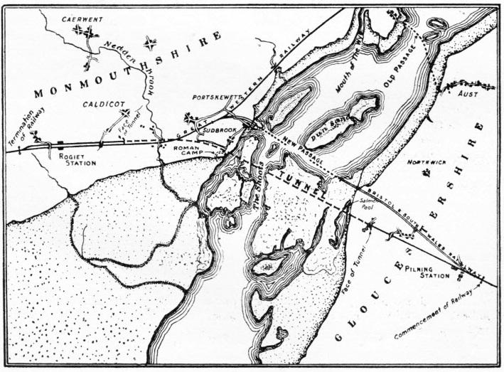
THE SEVERN ESTUARY, showing the line of the tunnel crossing, and also the Old Passage and New Passage ferries.
You can also read more on “The Channel Tunnel”, “The Great Apennine Tunnel” and
“The Simplon Tunnel” on this website.
You can read more on the “Conquest of the Severn” in Wonders of World Engineering