Developments During the Second Half of the Nineteenth Century
DESIGN AND INVENTION - 2

FRANCE’S FIRST LOCOMOTIVE, built by Marc Seguin in 1829 for the St. Etienne-Lyon Railway. The tender carried two rotary fans, driven by the wheels, to provide a draught for the fire.
WE have traced, in an earlier chapter, the development of the steam locomotive from the experiments of Richard Trevithick in 1801 to the Rainhill Trials in 1829.
The success of George and Robert Stephenson’s “Rocket” paved the way for later improvements both in size and in details of design and construction. For ten years after the locomotive trials at Rainhill, improvements in railway engines followed quickly, largely due to the needs of the Liverpool and Manchester Railway.
Locomotive development was not, however, confined to Great Britain. Continental engineers were eager and willing to try out the new form of transport. The French were among the first to appreciate the advantages of the steam locomotive, and in 1829 the first engine built in France was completed.
The engine was designed by Marc Seguin, a famous engineer and scientist who was born in 1786 and died in 1875. He instituted the first steam-operated railway in France and, after considerable experiment, a multi-tubular boiler was patented by him in 1827. One of these boilers was fitted to his 1829 engine. The four-coupled wheels were 3 ft 8-in in diameter, driven by two vertical cylinders 9-in by 24-in, placed on either side of the boiler. The piston rods projected upwards and drove the wheel crank pins by connecting rods. The crossheads, guided by Watt parallel motions, operated the valves controlling steam to the cylinders. Hand levers were provided for reversing the locomotive.
The boiler, 9 ft long and 31-in diameter, had many novel and interesting features. The fire-grate was placed beneath the boiler-barrel and was water-jacketed at the sides, the hollow spaces communicating with the barrel through a bridge-casting at the front end. A double casting formed a flue leading from the grate to the chimney at the rear. The double-cased flue served also as a heater for the boiler feed water, which was delivered by two long-stroke pumps.
The ash-pit under the fire-grate was closed, air being blown in by two large rotary fans on the tender, driven by cords and pulleys from the wheels.
The framework of the engine was of wood, and the wheels had cast-iron naves with wooden spokes and felloes. The wheel tyres were of wrought iron. The engine weighed just under 6 tons in working order, and could haul 30 tons at 4½ miles an hour, on a gradient of 6 in 1,000.

THE “NOVELTY”, which attained a speed of nearly 32 miles an hour at the Rainhill Trials, is shown here as a scale model in part section. Note the upturned steam-collecting pipe and regulator valve to the left of the boiler. Fuel was fed through the central tube in the boiler to the fire. The top of this tube is provided with two shutters to prevent its use as a chimney. The gases of the furnace were discharged into the atmosphere through the pipe at the left of the picture.
A number of locomotives, similar to the “Rocket” but larger and heavier, were built in England between 1830 and 1840. As compared with the 8-in by 17-in cylinders of the “Rocket”, the “Northumbrian” had cylinders 11-in diameter by 16-in stroke. This large engine was more than twice the weight of the “Rocket”, and in 1830 led the opening procession on the Liverpool and Manchester Railway.

A SECTIONAL MODEL of the “Rocket” in the Science Museum at South Kensington. The blast-pipe in the chimney fire-tube in the lower part of the boiler, and the collecting pipe in the steam dome on top of the boiler are shown in this picture. The model represents the “Rocket” as it appeared at the Rainhill Trials in 1829.
The driving wheels of the “Northumbrian” were 5 ft diameter, and the main frames comprised iron plates to which were attached the “Horns” carrying the axle-boxes.
The “Planet” locomotive, also built in 1830, had cylinders the same size as those of the “Northumbrian”, but placed inside the smoke-box and worked direct on to a double-cranked driving axle. This locomotive had four wheels, a single pair at the front end and two driving wheels at the rear. The weight of the engine was 8 tons, and large numbers of this type were built for passenger work; others, for hauling goods trains, were fitted with four-coupled wheels.
 These goods engines were similar in design to Edward Bury’s locomotive “Liverpool” of 1831. This engine was fitted with two inclined cylinders, 12-in diameter by 18-in stroke, placed under the smoke-box. The four-coupled wheels had cast-iron hubs with wooden spokes and felloes and iron tyres. The driver’s platform was attached to the back of the firebox, which was domed at the top, and of D section instead of rectangular, as was usual at that time. This engine is said to have been capable of hauling 150 tons on a level track at 25 miles an hour.
THE ORIGINAL “ROCKET”. It will be seen on comparison with the picture of the model above that among other alterations the cylinders were lowered to a nearly horizontal position, before the engine ceased running, in 1844.
The difficulty experienced with all these four-wheeled engines, however, was the oscillation or “pitching” to which they were subject at moderate speeds, because of the short wheel base. In addition to this, the increasing traffic on the railways was demanding heavier engines than could be carried on four wheels. In 1833 the Stephensons overcame both difficulties by the introduction of a six-wheeled engine, the “Patentee”. This engine had a single pair of driving wheels with small carrying wheels at either end. The driving wheels were 5 ft diameter and were without flanges, to facilitate the negotiation of curves. The cylinders were 11-in diameter by 18-in stroke, and the weight of the locomotive was just under 11½ tons. The 1833 engine with the 2-2-2 wheel arrangement was standardized as a passenger locomotive and the type - with improvements and increase in size - was built in Britain for the next sixty years.
 THE “LIVERPOOL” Locomotive of 1831, which ran for a time on the Liverpool and Manchester Railway. This engine, designed by Edward Bury, had two inside cylinders 12-in diameter by 18-in stroke, and four-coupled 6 ft wheels. The firebox had a high-domed crown, and on the back was attached a platform for the driver.
THE “NORTHUMBRIAN” built by Robert Stephenson & Co, led a procession of trains at the opening of the Liverpool and Manchester Railway in 1830. This was the first locomotive in which the firebox was incorporated with the boiler shell.
THE “PYRACMON” locomotive was built by the Great Western Railway at Swindon in 1847 to the design of Sir Daniel Gooch. The engine was in service until 1872 and ran for 385,000 miles.
In 1835, only six years after the Rainhill Trials, the improved 2-2-2 passenger locomotives had cylinders 12-in or 13-in diameter by 18-in stroke with wheels 5 ft or more in diameter. Boilers at that time had about 400 sq ft of heating surface with a grate area of 10 sq ft and a working pressure of 50 lb per sq in. The average speed of passenger trains varied between 20 and 25 miles an hour with a load of about 50 tons.
Isambard Kingdom Brunel, the great engineer who planned the Great Western Railway from London to Bristol, foreseeing the need for higher speeds and greater loads, declared his intention in 1835 of adopting a broad gauge of 7 ft (plus ¼-in) instead of the 4 ft 8½-in of other lines. Broad-gauge engines were accordingly built by various makers for the new line, the best known of these being the “North Star”, which now stands in the great locomotive works at Swindon. This engine, when running between London and Maidenhead in 1838, hauled a load of 80 tons at a speed of over 30 miles an hour.
Brunel’s assistant, Daniel (afterwards Sir Daniel) Gooch, prepared designs for a series of engines similar to the “North Star”, and between 1840 and 1842 over sixty of these express passenger locomotives were built for the Great Western Railway.

AN AMERICAN ENGINE FOR AUSTRIA. This model locomotive made in 1843 represents a type designed in 1837 by William Norris of Philadelphia. The engines were used on the first Austrian railways, and many of this class were afterwards built at Vienna.
An improvement was made to locomotives in 1838 by an alteration to the slide valve controlling the supply of steam to the cylinders. The valve was lengthened so that steam was cut off from the cylinder before the piston had completed its stroke. This had the effect of using the steam expansively, so effecting economies in fuel. In addition, the improved valve permitted of a freer exhaust, a necessity in view of the increased speed of the piston.
The following year, a still further improved method was invented by Isaac Dodds for securing a locomotive boiler to the frames. Before 1839 it had been customary to bolt the boiler to the frames at both ends. When it became hot, however, the boiler expanded longitudinally, so imposing stresses on the frames. Dodds attached the boiler at the smoke-box only, allowing the firebox end to slide on the frames without lifting. This method is in use at the present time.
The Birmingham and Gloucester Railway in 1840 purchased some locomotives from America, built by William Norris of Philadelphia. These engines had a leading four-wheeled bogie with two driving wheels at the rear driven by cylinders 10½-in diameter by 18-in stroke.
A year later, Robert Stephenson patented a long-boilered locomotive with a barrel about 11 ft 3-in in length. The average length of a locomotive boiler at that time was 8 ft 6-in, and the additional length was provided to make better use of the fire tubes as heating surfaces. Engines of this type proved successful, and large numbers were built between 1841 and 1845.

EDWARD BURY’S ENGINE of 1832 was an improvement on his four-wheeled locomotives, the rear trailing wheels preventing oscillation at high speeds. Engines of this type were employed exclusively on the London and Birmingham Railway from 1837 to 1846. In the latter year the model illustrated above was made.
The year 1845 marked an important period in locomotive development - a great impetus having been derived from the “Battle of the Gauges” on the Great Western Railway. Brunel, the company’s engineer, had laid out the line from London to Bristol with the 7 ft or “broad” gauge. The broad and narrow gauges met at Gloucester in 1845, and the inconvenience arising from the use of the two quickly became apparent. A Royal Commission was appointed in the same year to consider the fixing of a uniform gauge for all the railways in the country. The problem was thoroughly investigated by the Commissioners, who were inclined to favour the adoption of the narrow gauge as standard.
The question of the relative merits of the two gauges, from the locomotive point of view, was debated to such an extent, however, that Brunel suggested a series of trials between engines on both lines.

AN EARLY FRENCH EXPRESS ENGINE designed by T. R. Crampton, and built at Paris for the Northern Railway of France in 1849. Engines of this type worked the French express services until 1876. The driving wheels of these locomotives were 6 ft 10½-in diameter, and were placed behind the firebox.
These trials were carried out, but, although the broad-gauge engine could haul a heavier load than its rival or an equal load at higher speed, the narrow-gauge locomotive proved more economical to run.
The trials did not influence the Commissioners to any great extent, since the principal question involved related to the fixing of a standard railway gauge for the country. This was finally fixed by legislation at 4 ft 8½-in; and the Great Western broad gauge was abolished on May 20, 1892.
High Speeds in ‘47
For a few years subsequent to 1846, however, a keen rivalry existed between the engineers of both gauges, and many remarkable locomotives were designed and built in a competition for speed and power. The first of Gooch’s famous broad-gauge engines with a single pair of 8 ft driving wheels was built in 1846. This locomotive, the “Great Western”, with two cylinders, 18-in diameter by 24-in stroke, and a steam pressure of 100 lb per sq in, is said to have attained a speed of 59·3 miles an hour with a load of 100 tons between London and Swindon.
Advocates of the narrow gauge were responsible for an increased demand for high speed engines, and in May, 1847, a Stephenson long-boilered locomotive hauled a train from London to Birmingham at an average speed of 56 miles an hour. A maximum speed of 75 miles an hour was attained, and the last 21 miles of the journey were run at 60 miles an hour.
Another type of narrow-gauge engine, designed by T. R. Crampton, made its appearance in 1846, the first two having been built for the Namur and Liége Railway in Belgium. These engines were carried on six wheels with the 7 ft driving wheels behind the firebox. The size of the driving wheels did not, therefore, limit the size of the fire-grate. The cylinders were 16-in diameter by 20-in stroke. Engines similar to these were built for a number of British railways and remained in service until 1875.
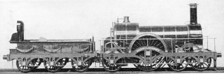
“HIRONDELLE”, one of the most famous engines made at Swindon Works for the Great Western Railway. This locomotive, built in 1848, ran 605,010 miles until 1873, and was designed by Sir Daniel Gooch for the Great Western broad gauge, which measured 7 ft ¼-in, between the rails. The broad gauge was superseded by the standard gauge of 4 ft 8½-in on May 20, 1892. No protection was provided for the driver and fireman, but the guard sat in a shielded seat at the back of the tender so that he could watch the train.
In France and Germany also these locomotives were very popular and nearly 300 were built for the Continent between 1846 and 1864.
The largest Crampton type engine was built for the old London and North-Western Railway in 1848. This locomotive had two cylinders 18 in diameter by 24 in stroke, and the driving wheels were 8 ft diameter. The weight of the engine was 35 tons, and it hauled heavy trains between London and Wolverton. A year before the building of this locomotive, the same company acquired the “Cornwall”, designed by Francis Trevithick. In the “Cornwall” the boiler was placed below the driving axle carrying a single pair of 8½ ft wheels.
In 1846, the first steam motor-coaches, designed by W. Bridges Adams for service on branch lines, were introduced. This type was at first built as a combined engine and carriage, but as the arrangement proved unsuitable in practice, a light engine drawing one or two carriages was substituted, and vehicles on this principle have been in service on railways all over the world until the present time.

AN ENGINE FOR INDIA, built at Leeds in 1856 for the Bombay, Baroda and Central India Railway. The design follows that of Alexander Allan for his “Crewe” class of goods locomotives built at Crewe works between 1843 and 1857. The outside inclined cylinders were 14-in diameter by 24-in stroke, driving four-coupled wheels of 5 ft diameter.
An important improvement in locomotive design was made by John Gray in 1838, when he patented a valve gear by means of which steam could be cut off from the cylinder at varying positions of the piston, so regulating the power of the loco- motive at different speeds.
In 1841 came one of the most important developments in the history of the locomotive. This was the invention of the “link motion” valve gear, a form of gear which is still in use to-day. It makes use of two eccentrics on the driving axle, one for running forward, the other for the reverse direction. The eccentric rods are attached, one at each end, to a curved “link” containing a slot in which slides a die-block attached to the slide valve of the cylinder steam chest.
By moving this link, so that the die block is either at the top or bottom of the slot, the starting direction of the engine is determined. A partial movement of the die block towards the centre of the link causes the supply of steam to the cylinder to be cut off before the piston has completed its stroke, so economizing fuel by using the steam expansively.
The gear was proposed by W. Williams, and after improvement by William Howe it was fitted by Robert Stephenson & Co. to a North Midland Railway engine in 1842.
The “Stephenson Link Motion”, as it has been named, was the forerunner of other valve gears, notably those designed by Sir Daniel Gooch in 1843 and E. Walschaerts, of the Belgian State Railways, in 1844. Walschaerts’ valve gear is now used all over the world.
Improvements in locomotive detail and design have followed close in the succeeding years, and continue to be made - no engineer will admit to finality in the perfection of his machine.

BUILT AT CARDIFF in 1864, the engine shown here was designed by J. Tomlinson for passenger work on the Taff Vale Railway. The engine had “double” frames with the wheels between the two plates, so that the driving wheel axle ran in four bearings, one in each frame-plate. The leading wheels had outside bearings only.
You can read more on “The Story of the Locomotive 1”, “The Story of the Locomotive 3” and “The Story of the Locomotive 4” on this website.


