© Railway Wonders of the World 2012-23  |  Contents  |  Site Map  |  Contact Us  | Cookie Policy

Electric Locomotive Classification - 1

How Engineers Have Modified the Whyte System and the Various Wheel Arrangements in Service: The American Practice
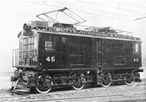

A 2,400-VOLT 0-4-4-0 ELECTRIC LOCOMOTIVE OF THE BUTTE, ANACONDA AND PACIFIC RAILWAY


A 2,400-VOLT 0-4-4-0 ELECTRIC LOCOMOTIVE OF THE BUTTE, ANACONDA AND PACIFIC RAILWAY. It scales 1 62,000 lb, and is driven by four General Electric Motors - one on each axle. Its American classification reads: 0440-E-162-4GE229A-2400.


WHEN electricity first set out to dispute the supremacy of steam traction it was generally believed that the Whyte system of classification, which had proved so conspicuously successful for denoting the type of established locomotive, might be effectively applied to the electric rival. But the vast difference between the two forms of power and the opportunity to “ring the changes” upon the arrangement of the wheels were found to be so extensive as to lead, within a very short time, to the production of a bewildering array of types incapable of ready, comprehensive identification by the time-honoured principle.


The electric differs very markedly from the steam locomotive. Whereas the latter is a self-contained mobile power station, producing its energy as required, the electric unit is merely a motor station, possible of active operation only so long as it is in direct touch through its collector with the channel, the conductor or third rail, across which the power is flowing from the

generating station placed at a central point. Consequently the electrical locomotive engineer has many overwhelming advantages over his steam colleague. He is not trammelled with such factors as cylinders, boiler, fire-box, water-tank and fuel bunkers. Their elimination releases so much more space for the installation of more power, the compression of the whole equipment of a given output within more convenient overall length, or permits the number of wheels to be increased for augmented adhesion.


Furthermore, the method of transmitting the power to the driving wheels is much more diverse. A motor may be mounted on each axle either to drive direct or through gearing, as if, in the steam engine, a pair of cylinders were connected to each driver; or one motor can be adapted to actuate a group of driving wheels through the conventional side-coupling rods. Again, unlike the steam locomotive, the electric can be driven with equal facility in either direction, and so, strictly speaking, has neither a front nor a rear end, although, during the very early days, strange to relate, there was a certain attempt to preserve this unavoidable characteristic of the steam locomotive.


Realizing the futility of attempting to apply the Whyte system of classification, pure and simple, to the electric locomotive, European manufacturers, by tacit agreement, decided upon a modification of the principle to meet the new conditions in the most comprehensive manner. Simplicity is preserved, with differentiation between the driving and non-driving axles, indication of the truck arrangement, and the coupling rod arrangement. The number of axles, not wheels, is set forth, as in the Continental application of the system to steam locomotives, but with the combination of numerical and alphabetical symbols; the former is used to indicate the non-driven, and the latter the driven axles.


If a motor be mounted upon the axle to drive it independently, then it is expressed by the letter “A”, the first letter in the alphabet, and indicating only one axle; if two axles are coupled then “B”, the second letter, expressing two axles, is used; “C”, the third letter, with three coupled axles in the one frame; “D”, the fourth letter, for four axles; and so on, though the number of driving wheels which can be accommodated in the one frame is as limited in electric as in steam practice.


If the locomotive should have a carrying axle at each end, with a single driving-axle between, it would be classed 1-A-1; while a six-wheels coupled, without carrying axles, would be 0-C-0. Translating steam locomotives into the electric classification, the “Atlantic” would be known as 2-B-1; the “Pacific” as 2-C-1; and the “ten-wheeler”, with its three-coupled axles, as 2-C-0. Under this Continental system the North Eastern high-speed passenger electric locomotive, classed in Great Britain as 4-6-4, becomes 2-C-2.


It is not only possible to introduce every wheel arrangement known to steam practice into the electric locomotive, but to create an imposing array of further types merely by varying the disposition of the wheels. For instance, the driving wheels may be divided into groups each carried in its own truck, and the latter may or may not be articulated. Consequently the “Duplex”, “Mallet”, “Triplex” and even “Quadruplex” types of steam locomotive may be introduced with ease. Yet, at the same time, it is necessary to indicate this grouping, and that without depriving the classification principle of its cardinal simplicity. This is accomplished readily. If a group of four-coupled axles be divided in twain, with articulation, then the letter “D” employed to designate the first-named arrangement is changed to “B + B”, the plus sign intimating articulation. On the other hand, should the trucks not be articulated, then the minus sign is used, and we get “B - B”.


The advantage of this modified Whyte system to meet electric conditions, by the inclusion of alphabetical symbols, which from their position in the alphabet also have a relative numerical value, may be readily illustrated. Take the “Mikado” steam locomotive with its classification 2-8-2, expressed on the Continent, from counting the axles, as 1-4-1. In the electric locomotive this might be presented as 1-AAAA-1; 1-AA+AA-1; 1-AA-AA-1; 1-B+B-1; 1-B-B-1; or 1-D-1.


The first designation would denote that the engine had four driven axles, but each carrying its own motor; the second shows that there are four separately driven axles, but disposed in two groups, and, according to the plus sign, the frames are articulated. In the third case we have the same wheel disposition, but without articulation of the frames. The fourth classification indicates that the four drivers are divided into two groups of two coupled axles each, with articulated frames; whereas in the fifth instance we still have this arrangement, but according to the minus sign there is no articulation. Finally we have the four driving axles coupled into the one unit, “D” being the fourth letter in the alphabet, and so we obtain the straight electrical counterpart of the “Mikado” of steam practice.


The foregoing do not exhaust the possible arrangements of the wheels in this single instance, but will suffice for our purpose. Incidentally, it may be mentioned, when setting out the classification in this manner, there is no need to introduce the letter “E” to intimate reference to an electric locomotive; this fact is automatically conveyed by the employment of alphabetical symbols.


In only one respect is it possible to simplify this system, and that is in the case of the direct driven axles. The electric

reproduction of the “Decapod” with five separately driven axles might be just as explicitly expressed “5A” as “AAAAA”, the general method under existing conditions. The former indication of the five separately driven axles, representing the one-axle-one-motor principle, is less cumbersome. In contemporary practice the wheel arrangement may, as a rule, be read from either end of the electric locomotive. From the fact that it is not necessary to take it to the turn-table, the end guiding trucks are, for the most part, symmetrical - either two- or four-wheeled.


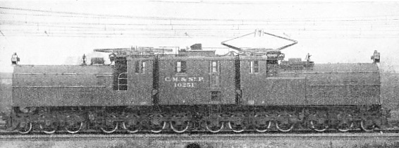
International General Electric gearless locomotive with 28 wheels, used for hauling the Chicago, Milwaukee and St. Paul’s Railway expresses over the Cascade Mountain division

GIANT AMERICAN PASSENGER 3,000-VOLT ELECTRIC. This International General Electric gearless locomotive has 28 wheels, and is employed for hauling the Chicago, Milwaukee and St. Paul’s Railway expresses over the Cascade Mountain division.


The foregoing system is acknowledged throughout France, Germany, Italy, Sweden and Switzerland, but with the extensive adoption of electric traction in the United States the domestic manufacturers introduced a new and individual classification. It represents, in principle, the Whyte classification so far as the conditions permit, and is based upon the assumption that every locomotive has three trucks - a guiding truck at each end, with the main driving truck between. The number of wheels in each are expressed in sequence as in the case of the steam locomotives. This is followed by the letter “E” to denote electric; the weight of the locomotive in thousands of pounds; the motor equipment according to its commercial rating by the manufacturers; and, finally, the voltage of the line. Thus the huge electrics hauling the trans-continental passenger and freight trains of the Chicago, Milwaukee and St. Paul Railway through the Cascade Mountains are described as 6886-E-530-12GE-100A-3,000 and 462264-E-550-6W-3,000 respectively.


Interpreted, the former means that the locomotive has 28 wheels, with a group of six at either end and two groups of eight each in the centre; “E” signifies “electric”, as already explained; “530” gives the weight of the complete locomotive, namely, 530,000 lb; the following combination intimates that there are twelve motors of the General Electric standard type; finally we learn that the conductor carries current at 3,000 volts.


In the second instance we are informed that the locomotive is mounted on 24 wheels, comprising a four-wheeled truck at either end, followed by a truck carrying 6 wheels, and then a two-wheeled truck. In actual truth there are two trucks; the wheel arrangement of each represents our old friend the “Pacific” of steam locomotive design, the two trucks being set back to back. The succeeding letter “E” signifies “electric” as before, and the following group of figures the weight, in this instance 550,000 lb, followed by the intimation that there are six Westinghouse motors, with line working at 3,000 volts.


This classification is unwieldy, and at the same time lacks expressiveness. Thus, in the case of the General Electric loco-motive, only the number and truck grouping of the wheels are communicated, but no intimation is conveyed concerning articulation. Fourteen axles are indicated, but nothing pertaining to the disposition of the idle or non-driven axles or their number. One surmises, and correctly, there is one motor to each axle, and that twelve out of the fourteen axles are driven, so that the outstanding two idle axles are set at each end of the locomotive. The classification would be more enlightening if the steam locomotive method were slavishly followed, giving the reading 2-4-8, 8-4-2. This would indicate the carrying axle at each end, but be misleading in regard to the truck arrangement.


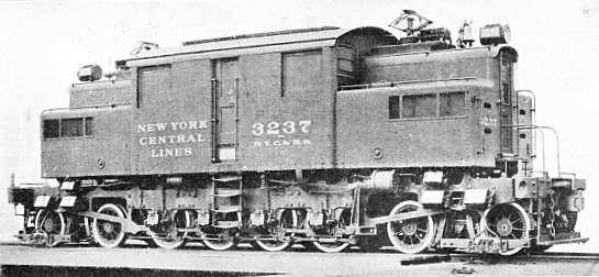
LATEST TYPE OF EXPRESS ELECTRIC LOCOMOTIVE ON THE NEW YORK CENTRAL SYSTEM


LATEST TYPE OF EXPRESS ELECTRIC LOCOMOTIVE ON THE NEW YORK CENTRAL SYSTEM. It has four trucks, each carrying two axles, with a motor mounted on each axle, and scales 250,000 lb. Its American classification reads: 4444-E-250-8GE91A-600.


In the case of the Westinghouse the information offered is more intelligible, and for this reason it is frequently described as the “double-Pacific”. The incorporation of the origin and character of the electrical equipment, though possibly interesting, might advantageously be omitted if only for the sake of simplicity. It is not observed in steam practice nor in Europe in connexion with electrics, and its purpose is superfluous except to the manufacturers.


The superiority of the European classification system is convincingly demonstrated in this instance. Thereby the 28-wheeled - fourteen-axle - American locomotive would be expressed 1-AA+AAAA+AAAA+AA-1, capable of further simplication to 1-2A+4A+4A+2A-1, showing the end driving trucks, the subdivision of the drivers into groups, the one-axle-one-motor principle and articulation of the trucks. The Westinghouse would be set out 2-C-1+1- C-2, showing the three driving axles in each group as being coupled with articulation of the trucks.


The arrangement even permits direct application of the Whyte system, if desired, by substituting the number of wheels instead of axles as followed in Europe; the reading in this instance would be 4-F-2+2-F-4. There is no necessity in this instance for the distinguishing letter “E” because, as already explained, alphabetical notation for the coupled axles in itself intimates the electric locomotive. Moreover, its suppression leaves the way clear for the use of the letter “E” to denote the number of driving axles in the one group when this, in electric as in steam practice, is applied to the mounting of five coupled drivers in one frame.


Owing to the American classification system being so cumbersome and, to a degree, misleading, it is not meeting with general appreciation, even in the United States, while it is generally ignored outside the country. It is probable that the Whyte system, pure and simple, will prevail, with the index letter “E” to signify electric, though the increasing vogue of the European combined alphabetical and numerical system will possibly lead to its general adoption. Its basic principle successfully precludes all possibility of the electric being confused with the steam locomotive.
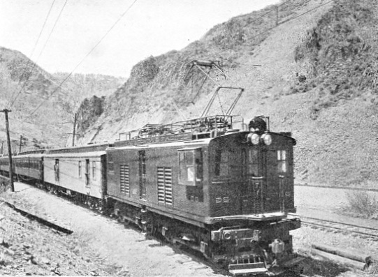

STANDARD PASSENGER TRAIN ON THE BUTTE, ANACONDA AND PACIFIC RAILWAY


STANDARD PASSENGER TRAIN ON THE BUTTE, ANACONDA AND PACIFIC RAILWAY. The average passenger train consists of one mail and baggage coach, and two to four coaches, and is hauled by a 0-4-4-0 locomotive. Direct current is supplied through the overhead conductors at 2,400 volts.


One of the first successful main line electrification schemes to be completed was that of the Butte, Anaconda and Pacific Railway, running between Butte and Anaconda in Montana. This American road, although only 25·7 miles in length, but with sidings and double track aggregating 122 miles, handles an enormous volume of traffic, the bulk of which is mineral - ore moved from the mines at Butte to the smelters at Anaconda. Direct current is supplied through the overhead conductors at 2,400 volts. The locomotives are of the 0-4-4-0 type, weighing 162,000 lb, driven by four General Electric motors mounted on the four driving axles. Those used for freight service are identical with the passenger engines except in regard to gearing. The former are geared to operate normally at 40 to 50 miles per hour; the latter at 15 to 25 miles an hour.


Each motor develops 300 horse-power, so that the total output of the unit is 1,200 horse-power. At a speed of 15 miles per hour the freight locomotive develops a tractive effort of 25,000 lb at 15 miles per hour, but it is capable of exerting a maximum draw-bar-pull of 48,000 lb for 5 minutes. In service two of these locomotives, coupled together to form a single unit, handle ore-trains of about 70 cars, and weighing approximately 5,000 (American) tons.


The electric fleet of this system has displaced 27 steam-locomotives ranging from “Mastodons”, scaling 316,000 lb, with 166,000 lb on the drivers, to passenger locomotives scaling 264,000 lb complete, with 120,000 lb on the drivers. The average passenger train is composed of one mail and baggage van, and two to four coaches, according to the density of the traffic, and the journey of 25·7 miles between Anaconda and Butte, with its grades running up to 15·6 feet per mile occupied one hour under steam haulage.


The whole of the steam locomotive equipment has been abandoned, and, although the schedule timing for the passenger trains has not been reduced, though easily feasible under electric conditions, there has been an immense saving of coal. This is a matter of primary importance to this district, since all mineral fuel has to be hauled at least 400 miles, and costs the railway approximately 17s. 6d. per ton delivered. Not only are the electrics, under “double-heading” - they then constitute a single unit by virtue of the coupling-up of the controls of the following locomotive to the cab of the pilot - able to move heavier loads, but they can cover the distance in shorter time. The revised schedule shows an advantage of 40 minutes, or 27·5 per cent, in favour of the new locomotives.


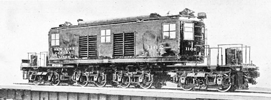
AN EARLY 4-8-4 ELECTRIC LOCOMOTIVE FOR THE NEW YORK CENTRAL RAILWAY


AN EARLY 4-8-4 ELECTRIC LOCOMOTIVE FOR THE NEW YORK CENTRAL RAILWAY. The first electrics were of the 2-8-2 type, but for easier running on the curves, four-wheeled bogie trucks were substituted, giving the 4-8-4 classification. Each axle was directly driven, and the armature was mounted on the axle.


As the result of the terrible calamity with appalling loss of life which befell an express in the tunnel approach to New York City, owing to the signals being obscured by smoke and steam from passing trains, the New York Central and Hudson River Railroad was compelled to convert the approach from steam to electric working. A certain period was set down for the carrying out of the statutory obligation. This involved the conversion of 54 miles of route - 268 miles of single track - extending from the Grand Trunk Terminal to Harmon on the main line, and to North White Plains on the Harlem Division.


The first electric locomotives were of the 2-8-2 type, but for easier and safer running round the curves the pony trucks were substituted by four-wheeled bogie trucks giving the wheel arrangement 4-8-4. Each axle was directly driven; the armature was mounted on the axle, and with the field arranged in such a manner as to permit the necessary vertical movement of the former.


Increasing train weights and the subjugation of the grade of 1 in 100 commencing from the terminal demanded greater starting effort, which, in turn, compelled the use of larger, heavier and more powerful locomotives of quite a new and original type - 4-4+4-4. There are four trucks, each carrying two axles, and a motor is mounted on each axle. But the two end trucks, nominally designed for guiding duty, are also driving trucks for the purpose of obtaining greater starting effort.

The body is supported on the two central trucks, the nose at either end projecting over the inner axle of each “driving-guiding” truck. In order to enable the sharp curves to be negotiated the middle truck is articulated in the centre.


The total weight of the locomotive is 250,000 lb, and the whole of this is available for adhesion. Under continuous rating the locomotive develops 2,000 horsepower and a tractive effort of 14,000 lb, capable of being increased for one hour to 2,600 horse-power and 20,000 lb of tractive force. The maximum draw-bar-pull, as, for instance, when starting, is 75,000 lb.


NEW YORK CENTRAL “20TH CENTURY LIMITED”


NEW YORK CENTRAL “20TH CENTURY LIMITED”. This luxurious nine-car all-steel train being hauled by a T-2-B Electric, which is capable of notching 75 miles per hour, and handling unaided a train of 1,200 tons on the rise of 1 in 100 out of the Grand Central Terminus.


These locomotives haul the Empire State Express, the famous New York Central “Limited,” a nine-car all-steel train, between the New York terminus and Harmon, the limit of the electrified zone on the main line, and are capable of attaining a speed of 75 miles per hour, as well as handling, unaided, a train of 1,200 tons up the rise of 1 in 100 leading out of the Grand Central terminus. The fleet comprises 73 of these high-speed gearless passenger locomotives which, during the year, cover approximately 2,000,000 miles.


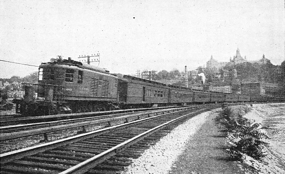
The New York, New Haven and Hartford Railroad has running powers over nine miles of the New York Central tracks to enter the city terminal, and, as the last-named has the third rail conductor, whereas the former favours the overhead system, the locomotives are equipped with both types of current collector. The bow is lowered automatically simultaneously with the application of the shoe to operate on the third rail when the latter is reached in the approach to the city, and vice versa on the outward journey, the change-over being made at full speed. The electrics of the New York, New Haven and Hartford Railroad are for the most part of the 2-4-4-2 type, and range from 204,000 to 273,000 lb in weight. They develop from 1,125 to 1,400 horse-power, and a tractive effort of 6,400 to 14,800 lb under continuous rating, with a maximum of 40,000 lb at starting.


The electrification of the approach to New York City and the Grand Central terminus has bestowed one overwhelming advantage upon the community, and has reacted to the advantage of the railway company. Under steam conditions the terminal yard was a dreary open depression in the heart of the city, whence rolled immense volumes of steam and smoke the livelong day from the scores of locomotives engaged in the multifarious duties incidental to a large humming terminal. It was an eyesore, while the value of the ground thus occupied represented millions sterling. With electrification the New York Central decided to rebuild the station, and to turn the many benefits accruing from the use of the alternative energy to full account.
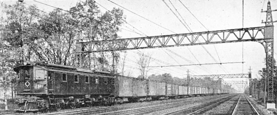

MAIN LINE ELECTRIC FREIGHT LOCOMOTIVE AND TRAIN ON THE NEW YORK, NEW HAVEN AND HARTFORD RAILROAD


MAIN LINE ELECTRIC FREIGHT LOCOMOTIVE AND TRAIN ON THE NEW YORK, NEW HAVEN AND HARTFORD RAILROAD. This Baldwin-Westinghouse electric is of the 2-4-4-2 type, and weighs 220,000 lb.


An imposing station has been raised and the tracks have been disposed in two tiers - the upper for the main line trains, the lower for suburban traffic and the sidings inseparable from a terminus. For the easier working of the local trains a huge loop is provided, thus dispensing with the necessity to back out. The steam and smoke nuisance thereby completely suppressed, the necessity to expose the terminal yard to the open air no longer prevailed. Accordingly, it has been covered, and upon this roof hotels, blocks of flats, and other huge buildings have been erected. The bulk of the traffic moves about the terminus beneath these buildings; only here and there is it possible to detect, from the street level, the steel arteries of one of the busiest and largest terminal stations in the country.


The most ambitious and comprehensive main line electrification scheme yet carried out in the United States is that of the Chicago, Milwaukee and St. Paul Railway. This embraces the Rocky Mountain and Cascade Mountain divisions of the line converted to this form of power, aggregating 646 miles of route and 858 miles of track. The power units are among the largest and most powerful yet designed. They are capable of moving passenger trains, composed of 12 to 14 steel coaches, over the heaviest banks rising 1 in 45·4, and, in exhibition speed tests, have notched 83 miles per hour.
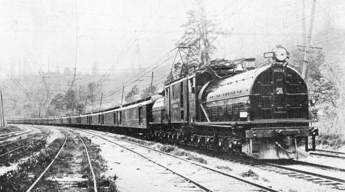

THE “SILK TRAIN” EN ROUTE SEATTLE TO NEW YORK


THE “SILK TRAIN” EN ROUTE SEATTLE TO NEW YORK. Cargoes of silk imported from China are landed at Seattle, loaded into a 15-steel-car train, and hauled by a 260-ton, 3,000-volt passenger locomotive across the mountain divisions without helper servicess. The contents of the load are valued at £900,000 to £1,000,000.


One of the most notable and interesting movements is the “Silk Train”, so-called from the fact that it is composed wholly of cargoes of silk imported from China landed at Seattle and moved across the continent to New York City. It runs regularly, and is often composed of 15 steel cars with contents varying from £900,000 to £1,000,000 in value, and is handled over both mountain divisions by a single locomotive.


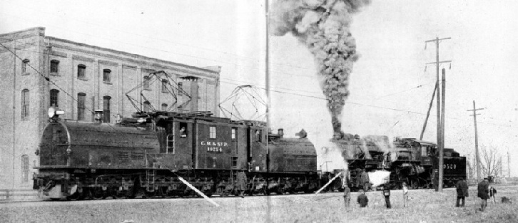
To determine the precise supremacy of the electric over the steam locomotive, many interesting-demonstrations are carried out from time to time. On one occasion the officials of the railway pitted one of the gearless passenger electrics, weighing 520,000 lb, against a freight “Mallet” weighing 556,000 lb. The two locomotives were set buffer to buffer, and the drivers were instructed to push one locomotive against the other for all they were worth.


A 265-ton gearless passenger electric locomotive is seen pushing against a 278-ton freight steam locomotive.


A NOVEL TEST FOR TRACTIVE EFFORT. A 265-ton gearless passenger electric locomotive is seen pushing against a 278-ton freight steam locomotive for mastery. The electric won and forced the Mallet backwards, although the latter was steaming its utmost to hold its ground.


The spectacle was impressive. The “Mallet” coughed and snorted, belching a huge plume of smoke and steam high into the air, the while the motors of the electric droned monotonously. The driver of the “Mallet” let his engine “all out”, but in vain. Instead, although he crowded on every ounce of steam, he found it impossible to hold his ground.


For a few seconds the two power units locked tightly together stood still; then the electric gaining the upper hand, the ponderous powerful “Mallet” was slowly but surely forced backwards. The steam unit was given every opportunity to excel; the rails were liberally sanded to prevent the driving wheels from slipping, but the continuous rotary torque of the electric proved overwhelmingly superior to the reciprocating and pulsating torque of the steam giant. The latter was further handicapped by having a much larger percentage of its weight supported on idle wheels, whereas in the case of its rival twelve out of its fourteen wheels are drivers.


Another demonstration of a vastly different character was carried out to prove the possibilities and efficiency of regenerative braking. Two steam locomotives, the one a high-speed passenger unit of the “Pacific” class having 173,000 lb on its drivers, and the other a freight locomotive of the “Mountain” type with eight driving wheels carrying 234,000 lb, were coupled to the Chicago, Milwaukee and St. Paul Railway’s 6-8-8-6 electric, the latter leading. They started off. When all three had been accelerated to a speed of 25 miles an hour the driver of the electric moved his regenerative braking controller to the “on” position; his purpose was to hold the three coupled locomotives to that speed, while the drivers of the two attached steam locomotives were instructed to force the electric beyond that speed - if they could.


The steam engines were given “full steam ahead”, but to no avail. All the excess power applied over and above that required to maintain 25 miles an hour was absorbed by the motors - now converted into generators - of the electric to be transformed into electric current and returned to the powerhouse. Some idea of the enormous effort put forth by the steam locomotives may be realized from the fact that at times as much as 2,700 horse-power was returned to the power-house - excess power converted into electricity turned back into the electric generating station for other uses.
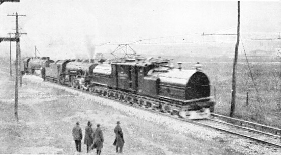

ELECTRICITY VERSUS STEAM


ELECTRICITY VERSUS STEAM. To demonstrate the efficiency of regenerative braking, one of the Chicago, Milwaukee and St. Paul’s gearless passenger locomotives was coupled to two giant steam locomotives. When a speed of 25 miles per hour was attained, the regenerative brake of the electric was put on and the other two driven at full steam in an effort to push the electric beyond that speed. It failed: the 25 miles per hour was maintained and the excess power returned to the power-house.


You can read more on “Electric Locomotive Classification 2”, “Electric Traction”, “Electrification in Europe” and “Electrification Overseas” on this website.