
© Railway Wonders of the World 2012-


Part 27


Part 27 of Railway Wonders of the World was published on Friday 2nd August 1935.
This issue contained a colour plate illustrating LMS Royal Scot No. 6110 "Grenadier Guardsman". The colour plate was attached to page 845, or the fifth page of this number. This plate had previously appeared as the cover to part 8.
The Cover
The cover of this week’s part shows one of the Great Western “King” class engines, “King Henry VII”, which has been streamlined to reduce air resistance at great speed.
 “King Henry VII” had previously appeared in the article on Locomotive Speed Records.
Click on the small image to see a short British Pathe newsreel clip of the streamlined locomotive.

“Grenadier Guardsman”
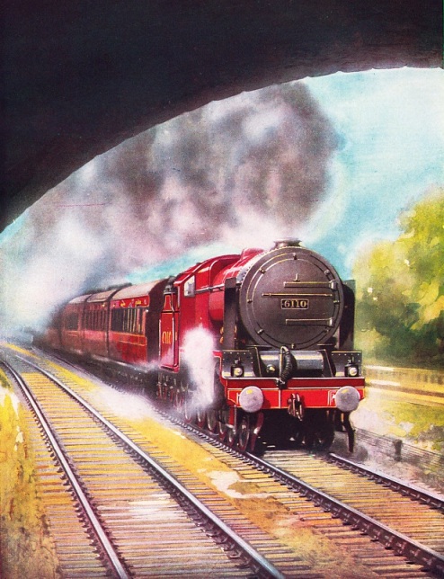
GRENADIER GUARDSMAN”, one of the LMS “Royal Scots”, at the head of the 10.30 am express from Euston to Manchester. Locomotives of the “Royal Scot” class have the 4-6-0 wheel arrangement, with 6ft 9in driving wheels. The three cylinders are
18 in diameter by 26 in stroke. The total heating surface is 2,480 sq ft, the grate area 31.2 sq ft, and the working pressure
250 lb per sq in. Tractive effort (at 85 per cent working pressure) is 33,150 lb. The total weight of engine and tender in working order is 127 tons 12 cwt.
This plate previously appeared as the cover for part 8.
(attached to page 847)
Progress in Rhodesia
An important railway system in the heart of Africa. This chapter describes the progress made by the railways during the early years of the twentieth century. One of the most spectacular feats of railway engineering in Africa was the building of the 1,300 ft-long bridge across the Kafue River. Material had to be transported some 2,000 miles up country from Cape Town to the site of construction. The details of the main routes, and a comprehensive journey up through Southern and Northern Rhodesia, together with the most important features of the railways in the country, mentioning the flood difficulties, the modern equipment, the principle workshops, are all covered in this chapter. This is the ninth article in the series Railways of the Empire. The article is concluded in part 28.
(Pages 867-868 )
Locomotive Valve Gears (1)
The control of steam in a railway engine. Further details about the well-know types of valve gears. This part covers Stephenson’s gear, the Gab gear, and Allan’s straight link motion. This is the ninth article in the series Design and Invention. Concluded from part 26.
(Pages 837-838 )
The Railways’ Daily Work
The widespread activities of four great companies. During every minute of the twenty-four hours, the engines of the four chief British systems travel an average of nearly one thousand miles. Did you know that the largest single item of traffic carried by the British railways is coal? It is said that a line built in 1602 at Newcastle for the haulage of coal was the beginning of the railway. During 1934 the British railways carried over half a million tons of coal, coke, and other fuel every working day. Another vital activity of the British railway companies is the management of docks. The importance of this special side of railway working may be judged from the fact that the total length of quay controlled by the companies amounts to approximately one hundred miles. Railway-owned steamers also play an important part in the commercial life of Great Britain. Each of the four main systems has marine interests and connexions. The total railway-owned fleet, apart from ships operated by the railways for other owners and those on one or two cross-Channel routes, is over 140 vessels. Hotels, vehicles for road transport, canals, the ownership of land, and control of house property are among the other branches of railway work mentioned in this chapter.
(Pages 845-852 )
Engineering Equipment
Speeding up modern railroad construction. The “machine guns” of the railway engineer - rock-drills, boring machines, pile drivers, and machine riveters. The world’s trans-continental lines, the great railway tunnels such as the Simplon, and the eight-miles tunnel of America through the Cascade Mountains, could never have been constructed without these invaluable aids to construction. The article is a sequel to that on The Track’s Heavy Artillery which appeared
in part 15.
(Pages 860-866 )
Contents of Part 27
Locomotive Valve Gears (1) (Part 2)
Perth General Station
“Grenadier Guardsman” (colour plate)
The Railways’ Daily Work
The Story of the Locomotive (3)
Engineering Equipment
Progress in Rhodesia (Part 1)
Allan’s Straight Link Motion
ALLAN'S STRAIGHT LINK MOTION, designed in 1855, made use of two eccentrics for forward and reverse gear. The reversing lever shifts the link, which is straight and not curved as in the Stephenson and Gooch gears, and at the same time moves the die block attached to the valve rod seen at the right of the picture.
(Page 837)
Perth General Station
The hub of the Scottish main lines. Situated in the centre of Scotland, it is the meeting place of lines from Edinburgh, Glasgow, Aberdeen, and Inverness. Perth Station formerly served the Caledonian, the North British and Highland Railways. To-day the junction is shared and jointly owned by the LMS and the LNER. By day and night Perth Station is a centre of activity. Between 4.45 and 6 am, for instance, expresses converge on the station from all directions. Details of the station layout, the characteristics of the different approaches, interesting facts about the principal trains which pass through, the locomotive depots, and many of the notable engines which have been and are now to be seen at this station, are included. This is the third article in the series Famous Railway Centres.
(Pages 839-844 )


Perth General Station
AT THE PLATFORM of Perth General Station. The length of the platform faces totals 7,700 ft. The greater part of the station is covered by a roof of steel and glass. At the head of the train illustrated is seen one of the efficient new Stanier 4-
(Page 839)
Paddington Goods Station
THE GOODS STATION at Paddington, the London terminus of the Great Western Railway. In one year the British railways carried over 260,300,000 tons of freight, and the freight train mileage in 1934 was 128,683,000. The goods shed at Paddington contains fourteen main tracks arranged in pairs with a platform 600 ft. long between each pair. The total amount of steelwork in the roof and columns is 1,600 tons. This goods station possesses all the latest loading devices.
(Page 845)
The Story of the Locomotive (3)
Developments during the second half of the nineteenth century. This is the tenth article in the series Design and Invention. You can read more on this period in G. Sekon’s The Evolution of the Steam Locomotive (1899).
(Pages 853-859 )


The Story of the Locomotive - 2
(Top) LONDON-
(Middle) A METROPOLITAN TANK on the London and North Western Railway. Numerous engines of this class were built by Beyer Peacock & Co. between 1864 and 1871. The cylinders were 17 in by 24 in and the coupled wheels had a diameter of 5 ft 9 in. The tank capacity was 1,000 gallons.
(Bottom) A NORTH EASTERN LOCOMOTIVE of the 492 class built in 1865 by Robert Stephenson & Co of Newcastle.
(Page 854)

Preparing the Way
PREPARING THE WAY for the track. Three tripod-mounted heavy drifter drills in action on a cutting near Barnet, in Vermont, USA. The dimensions of the drills vary from 2⅝ in to 4 in. Two men are generally needed to operate one of these powerful machines.
(Page 860)
