Further Methods of Distributing Steam to the Cylinders
DESIGN AND INVENTION - 14

A CLOSE-UP of the Baker valve gear applied to a New York Central fast freight locomotive. This gear was invented in 1903 and first used on a traction engine. It was later re-designed for a railway locomotive in 1908.
This chapter covers: the Baker valve gear, the Southern valve gear, the Young and Deeley valve gears and Miscellaneous valve gears.
WE have already seen in previous chapters that a slotted link, with a die-block working in it, provided the means of reversing and expansive working in the valve gears described so far. Now in all valve gears incorporating this link and die-block there is a certain amount of unavoidable error in the valve movements, due to the slipping of the die in the slot as the link oscillates. Though the amount is very small, it is persistent, and locomotive engineers, in their ceaseless efforts to attain the nearest approach to perfection, have given this matter a great deal of attention.
Valve gears have therefore been evolved which either use a stationary link, with a die-block which is moved only to reverse or notch up the engine, or else dispense with the link and die-block altogether. The most successful of the linkless valve gears is the Baker locomotive valve gear, which is used extensively in USA and Canada.
The Baker Valve Gear
The inventor of the gear, Mr. Abner D. Baker, an American engineer, first applied it to a traction engine in 1903. It proved satisfactory even in its original form, and in 1908 it was re-designed for locomotive use, and fitted to an engine on the Toledo, St. Louis and Western Railroad. For two years or so the gear underwent various tests, and sundry alterations and additions were made to it. The outcome of the experimenting was the Baker valve gear in its modern form, the patents for which were granted in November, 1911. Once established, its merits were quickly recognized, and at the present time there are upwards of 14,000 locomotives in the USA and Canada fitted with the Baker valve gear. It has been adopted as the standard gear by many railroads, and the number is increasing.
At the first glance the action of the gear is not apparent to the casual observer, but a study of the gear in detail reveals that it is exceedingly simple. The principle on which it works may be easily understood by comparing it with the Joy gear described in the chapter beginning on page 1072. Instead of the radius rod being attached to a die-block working in a curved guide which can be tilted forward or backward, it must be imagined as connected to one end of a bar, the other end of which works on a pivot which can be raised or lowered, so that it may be set above or below the centre line of the motion.

NO SLOTTED LINK IS NEEDED by radial valve gears working on the Baker principle shown left. The valve rod is connected to the end of a radius bar swinging on a pivot, which is moved by the reverse lever as required. In mid-gear both ends of the swing of the bar are equidistant from the valve spindle, which therefore does not move.

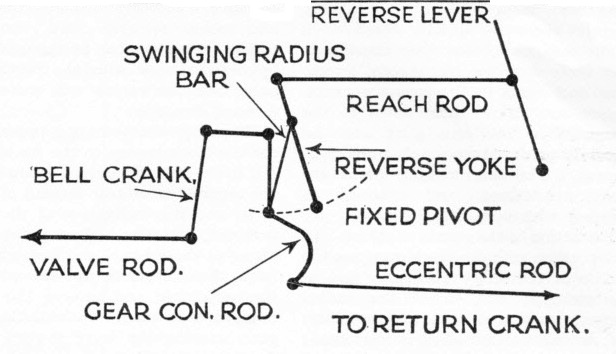
FOR FORWARD RUNNING the pivot is dropped below the centre line of the valve spindle, and the arc in which the end of the bar swings is inclined in the opposite direction. The highest point of swing is now nearest to the valve spindle; thus the opposite port is opened, and the engine will go ahead.
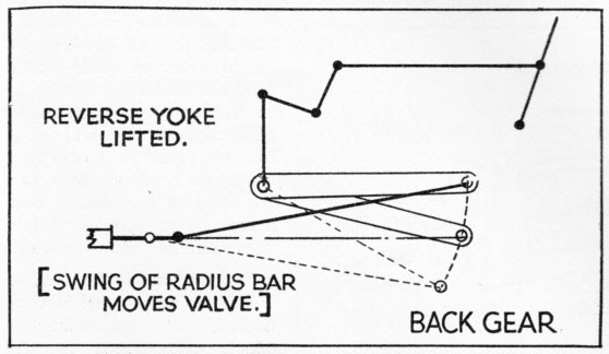
TO REVERSE THE ENGINE the pivot carrying the end of the swinging radius bar is lifted out of line with the valve spindle. As the bar swings, the end of the valve rod attached to it follows its movement and actuates the valve, the highest point of swing being farthest from the valve spindle.
The free end of the bar, to which the radius rod is connected, will describe an arc, which corresponds to the curved guide of the Joy gear. If the fixed end of the bar is below the centre line of motion, the upper end of the arc will be nearest to the cylinder, and the lower end farthest away from it; this corresponds to the forward tilt of the Joy shaft, and the engine will go ahead. If, however, the fixed end of the bar be raised above the centre line of motion, inclination of the arc is completely reversed; the upper end is now farthest from the cylinder, and the lower end is the nearest. The movement of the rod is now changed; the valve is reversed, and the engine will move backward.
In the Baker valve gear, the swinging bar - known as the radius bar - is arranged vertically for mechanical reasons, and the movement is transmitted to a horizontal plane by a bell-crank.
The Baker valve gear is “self-contained”, the principal working parts being mounted in a frame, either of girder or bracket pattern, which can be erected on the engine at the most convenient place. The gear set is standard for any engine; and, in the event of damage by accident, or other urgent need, the whole can be removed, and replaced by a fresh set taken from store, without taking the engine out of service. With ordinary valve gears, it usually means that the engine will have to spend two weeks or so in the shops while the parts are re-newed and refitted. In the gear frame are fixed the reverse yoke, radius bars, gear connecting rod, and bell-crank.
The reverse yoke is double, either side being pivoted at the bottom to a point in the frame, so that the yoke can be swung back and forth by a reach rod connected at one end to the top of the yoke, and at the other to the cab lever. The radius bars swing from pivots in the upper part of the reverse yokes, so that by inclining the reverse yokes either forward or backward, these pivots are set either in front or behind the centre line of the gear - corresponding to the “above-or-below” positions of the swinging bar mentioned in the explanatory paragraph above. The gear connecting rod - known to enginemen as the “sickle-rod” on account of its shape - is connected to the swinging ends of the radius bars at a point near its middle. The upper end is coupled to the horizontal arm of the bell-crank, the vertical arm of which is connected to a Walschaerts-type combination lever by a short rod called the valve rod. The “sickle” end of the gear connecting-rod is actuated by a return crank and eccentric rod, of exactly the same pattern as used to actuate a Walschaerts expansion link.
The working is as follows. When the cab lever, and consequently the reverse yoke, is in mid-position, the radius bar pivots come in line with the point where the gear connecting-rod is coupled to the bell-crank (except for a slight offset introduced for constructional reasons). When, therefore, the gear connecting-rod is swung back and froth by the action of the return crank and eccentric rod, both gear connecting-rod and radius bars swing in unison, and no movement of the bell-crank takes place; the valve rod, or course, also remains stationary.
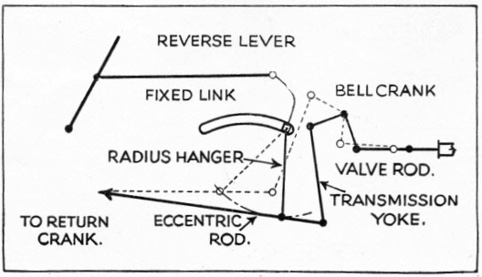
THE BAKER VALVE GEAR shown with the rods separated to illustrate the action. The gear connecting rod, being fixed by its middle to the bottom end of the radius bar, follows the swing of the latter, and pushes the bell-crank arm up and down, thus actuating the valve.
As soon as the reverse yoke is thrown forward, the radius bar pivots move to a point ahead of the centre line of the gear; the bottoms of the radius bars swing in an inclined arc instead of a horizontal one; consequently the gear connecting rod, attached to them by its middle, follows their swing and moves bodily up and down. The top of the gear connecting rod, being attached to the bell-crank, causes this to move also, the vertical arm of the bell-crank oscillating in the same direction as the gear connecting rod. If the reverse yoke is pulled back, the pivots come behind the centre line of the gear, and the inclination of the arc is reversed, causing the gear connecting-rod to push the bell-crank upwards on the forward swing instead of pulling it down. The vertical arm of the bell-crank now moves in the opposite direction to the gear connecting rod, and so reverses the valve movements. The greater the inclination of the reverse yokes, the greater the inclination of the arcs described by the radius bar ends, and consequently the greater the valve travel. The engine is notched up in the same way as any other engine, by bringing the reverse lever towards centre; this “flattens out” the inclination of the arcs, and causes the valve travel to shorten. There are no die-slip troubles with this valve gear. In view of that and of the ease with which wearing parts are renewed, it is rather surprising that there are no full-sized locomotives fitted with Baker valve gear in Great Britain, or indeed anywhere outside USA and Canada, where it has achieved such successful results. It has, however, found a hearty welcome in Great Britain among builders of miniature locomotives, because of its ease of construction and maintenance, and it is giving every satisfaction on hundreds of Lilliputian passenger-haulers.
The Southern Valve Gear
Everyone conversant with the history of the steam engine knows the story of the lazy boy who became tired of operating the valve cocks of a Newcomen pumping engine, connected up the cocks by pieces of string to the engine beam, made it self-acting, and went off to play marbles. An American engine-driver devised the simple Southern valve gear, not because he wanted to go and play marbles, but because he was tired of the shortcomings of the valve gears on the various locomotives that he had operated from time to time. As with the Baker valve gear, this one has not been used outside America in full-size practice, but it gives every satisfaction in the land of its origin.
The Southern valve gear belongs to the “radial” group, and although it employs a link and die-block, there is no die-slip trouble, as the link is absolutely stationary, being bolted to the frame; the only movement the die-block receives is from the reversing lever of the gear. The principle of the gear is very much the same as the principle described above, viz, the swinging bar, which is present in this gear. The stationary end of the bar is attached to the link in the die-block, while the moving end of the bar is directly connected to a return crank on the main crank-pin, by a long eccentric rod. This is prolonged beyond the connexion, the extreme end being coupled by a short rod to a bell-crank, which changes the motion from a vertical to a horizontal one, and operates the valve spindle direct.
The designer of the gear considered that there were too many rods, levers, pins, and joints in the ordinary gears. He set out to cut them down to the minimum in his own gear, and he certainly achieved no small amount of success. The few moving parts are easily maintained, and renewed as required with very little trouble.
HOW IT WORKS. The Southern valve gear employs a stationary link. When the reverse lever is pulled back, the die-block moves from one to the other end of the slot. The highest point of the arc described by the end of the radius hanger is then at the front, and the engine is reversed.
The action of the gear is as follows. In mid-position, the die-block occupies the middle of the link. The lower end of the swinging bar, called the radius hanger, oscillated by the eccentric rod, describes an arc which is horizontal; consequently the only movement transmitted to the bell-crank is that caused by the overhang of the end connexion, which moves slightly up and down in an opposite direction to the end coupled to the return crank. This overhang is so proportioned that the valve movement derived from it is just sufficient to open each port to “lead”.
When the die-block is pushed to the forward end of the link, the pivot of the swinging bar is pushed off centre, and, instead of the arc in which the lower end swings being horizontal, it is now inclined, with the highest point at the back encl of swing. Consequently the end of the eccentric rod attached to it also moves up and down, communicating the movement to the bell-crank by means of a rod called the transmission yoke, and the engine will travel in a forward direction.
When the reverse lever is pulled back, the die-block moves to the back of the slot in the link. The pivot is now behind the centre line of gear instead of ahead of it, and the inclination of the arc is reversed, with the highest point of the swing at the forward end instead of the back, thus reversing the movement of the bell-crank, and causing the engine to travel backwards. As with the Baker gear, moving the lever toward centre flattens out the arc, shortens the valve travel, and, by cutting off steam earlier, allows the engine to use the steam expansively.

THE SOUTHERN VALVE GEAR applied to a Midland Terminal eight-wheeled shunting locomotive. This gear was invented by an American engine-driver. It has not been used outside America in full-size practice, but has proved satisfactory in that country.
The Young and Deeley Gears
Although the Young and Deeley gears have not had the extended application of those described above, they are worthy of note because of their incorporation of an ingenious idea. In all the preceding gears, the primary movement has been derived either from eccentrics or from return cranks, set at (or near) right angles to the main cranks. The designers of the Young and Deeley gears do not use separate return cranks to operate their expansion links, but take advantage of the fact that the main cranks of a normal two-cylinder locomotive are already at right angles to each other. Therefore additional cranks are not provided, and the expansion link of either set of gear is operated from the crosshead of the other cylinder, which gives a movement the same as if it were operated by a separate return crank and eccentric rod.
The only trouble is a minor one. When separate return cranks are used, they are both set to "lead" or "follow" the main crank, and both die-blocks are at top or bottom of the link together, according to the direction in which the engine travels. If, however, the right-hand main crank "leads" the left-hand, it naturally follows that the left-hand crank "follows" the right-hand; and, with one crank "leading" and one " following", one die-block has to be at the top of the link and the other at the bottom, whichever way the engine runs. This introduces a complication in the reversing shaft. This has to be double in the Young gear; in the Deeley gear the two links have to be set out of line. The Young gear is used on outside-cylinder engines, and the Deeley gear on those with inside cylinders.

THE YOUNG VALVE GEAR derives its motion from the crank on the other side of the engine, instead of from a separate return crank set at right angles to the main crank. This diagram shows how the movement is transmitted across the frames.
The action of both gears is very much the same as the Walschaerts gear. In the Young gear the expansion link is mounted in the same way, but has a long tail, which is directly connected to the crosshead by a union link. The radius rod works on a short lever attached to a cross-shaft which transmits the motion to the other side of the engine, where a similar short lever is provided. The combination lever is mounted on this, upside down, merely as a matter of mechanical convenience; it is easier to drive it from the top of the expansion link on that side by a direct rod, than to connect it to the crosshead. As each crosshead drives the link direct, as mentioned above, it is obvious that the movement of the combination lever must be the same, whether connected to crosshead or link.
The inverted head of the combination lever is connected to the valve spindle in the usual way. The reverse shaft is double, and has two pairs of reverse arms, one being connected to a solid inner shaft, and the other to a tubular outer shaft. A double reach rod is used; and, whichever way the cab lever is moved, the die-blocks go in opposite directions, one to top of link, and one to the bottom.
In the Deeley gear, as fitted to the "990" series of inside-cylinder 4-4-0’s on the Midland Railway, the expansion links occupied part of the space between the inside connecting rods, and were set one ahead of the other. This got over the reversing shaft difficulty, as one arm pointed forward and the other backward, operating see-saw fashion; but it introduced more complication, as the connecting links and rodding were of different lengths for each set of gear. There is, of course, nothing wrong with the steam distribution of either type of gear.
The Young Valve gear can be arranged to give a quicker opening and closing of the ports than the Walschaerts gear, with normal setting; but as each side of the engine is dependent on the other side for its primary movement, it means that, should any defect develop in one side only, the engine is rendered helpless, and cannot be operated on one cylinder only, as on an engine with independent gears. Though breakdowns are infrequent nowadays, nevertheless some prejudice exists, and the interdependence factor has been put forward as one reason why the gears have not been more extensively used.
Miscellaneous Valve Gears
In addition to the valve gears already described, there are a few miscellaneous gears, examples of which are found mostly on industrial locomotives engaged on short private lines such as colliery railways, and on engines used for works, depot, and dock shunting. The Hackworth gear, for example, designed by a relative of the famous Timothy Hackworth, of Stockton and Darlington Railway fame, employs a slide shaft and radius rods similar to the Joy gear, except that they are straight instead of curved. The die-blocks are moved up and down them by vertical rods operated either by eccentrics or return cranks.
When a locomotive with slide or piston valves actuated by a valve gear of ordinary type is running well notched up, cutting off steam quite early in the stroke, an unwelcome factor is introduced, inasmuch as the exhaust ports also close early, and the trapped steam causes excessive compression in the cylinders. An engine would often run with a much earlier cut-off than the usual 15 to 20 per cent common to express locomotives when running at speed with a well designed and correctly set valve gear; but if the driver attempted to notch up closer than this, a terrific knocking and pounding would result, probably causing hot big ends and damage to the valve gear.

CYLINDERS for a Great Indian Peninsula Railway locomotive. Steam to these cylinders is controlled by an oscillating cam valve gear.
Piston and slide valves being "one-piece" components, it is not feasible to cut off steam earlier without interfering with the exhaust also. To overcome this trouble, and to provide an independent exhaust, many engines are now provided with poppet valves, similar to those of internal combustion engines. These may be operated by the ordinary valve gear, or by a special arrangement of cams, as in a motor car provided with poppet valves. Everyone is familiar with the poppet valve; many readers have doubtless ground in the valves on their car engines after decarbonizing; a detailed description of a locomotive poppet valve would therefore be superfluous. Suffice it to say that it is merely a "grown-up edition" of the motor engine valve, usually larger in the head (which is usually double) and shorter in the stem, in proportion to size. The valve seatings are placed at either end of the steam chest, but are not formed in the casting itself, being made removable and pressed into place. They are thus easily renewed without affecting the life of the cylinder casting. Sometimes, as with aeroplane and racing engines, there are two inlets and two exhausts per cylinder.
In one form of the Lentz poppet valve gear, the inlet and exhaust valves are set horizontally at different levels. Each valve stem is actuated by a short vertical lever, the admission valve levers being pivoted at the top, and the exhaust at the bottom. Rollers are arranged in the centre of each lever; these come opposite one another, and the oscillating camshaft works between them. The end of the shaft projects through the steam chest, and is worked by an ordinary Walschaerts gear. By careful planning of the cam contours, the opening and closing of both inlet and exhaust valves can be arranged so that a close cut-off can be used without causing excessive compression.

A SOUTH AFRICAN RAILWAY ENGINE of the
4-8-2 type fitted with a rotary cam valve gear.
The Caprotti gear more closely follows automobile practice, as it uses a rotary camshaft and vertical valves. The valves are double-seated and arranged "upside down" at either end of the cylinder, being retained in place by the usual spring on the stem. Each valve is actuated by a bell-crank, the horizontal arm of which presses on the valve stem. The vertical arm of each bell-crank is furnished with a short centrally-pivoted lever carrying a small roller at either end. These bear directly on the cams, which are mounted on a shaft running between the rollers, the whole assembly being enclosed in a gearbox mounted on top of the cylinders.
Reversing and notching up are effected by altering the position of the cams, which are made to slide on the shaft, and are connected by an ingenious arrangement of rods and levers to a wheel-and-screw of usual pattern in the cab. The camshaft is rotated by a long cardan shaft with universal joints, driven by bevel gearing enclosed in a box on the driving axle. With the Caprotti gear, it is possible to cut off steam as early as one per cent of the stroke, without. any increase of compression; but a cut-off as early as this would not be needed except to "feed" the cylinders when running down a long bank at a high speed, when a little steam in the cylinders is desirable. With the high-speed schedules of the present day it only needs one or two slight signal checks on a fast run, to compel the driver to "let her out" a notch or two in an endeavour to regain lost time; and most enginemen will confirm that the ability of a valve gear to notch up to an exceedingly early, cut-off is seldom of much practical use. Hence the well-tried piston-valve, in conjunction with a correctly designed valve gear of normal type, still "holds its own" for most purposes.
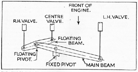
THE “TWO-TO-ONE” GEAR obviates the necessity for fitting a separate set of valve gears to the inside cylinder. The movement of the inside valve spindle is derived from the combined action of the outside spindles operating together through long and short levers on fixed and floating pivots respectively.
Because a locomotive may have three or four cylinders, it does not follow that it must have the same number of sets of valve gear. In the GWR "Stars", "Castles", and "Kings", the inside cranks are directly opposed to the outside cranks, and therefore all that is needed to operate the valves of the outside cylinders is a simple centrally-pivoted rocker connecting the inner and outer valve spindles. In a three-cylinder engine, however, such as the LNER "Pacifics", a conjugated or “two-to-one” (as the drivers call it) arrangement of levers has to be provided. A long horizontal main lever is pivoted near one end, and the longer end is connected to one of the outside valve spindles. A short lever, also horizontal, "floats" on a pivot at the other or shorter end of the main lever, the two ends of the short lever being connected to the other outside valve spindle and to the inside valve spindle respectively. This gear was designed by Mr. H. N. Gresley, Chief Mechanical Engineer of the LNER.

THIS ILLUSTRATION SHOWS the front end of a Federated Malay States Railway S or S2 Class Pacific locomotive showing the arrangement of levers for actuating the three piston valves from two Walschaerts valve motions on three-cylinder engines.
You can read more on “Locomotive Valve Gears”, “Locomotive Valve Gears - 2” and “The Shay Geared Locomotive” on this website.


